Overview
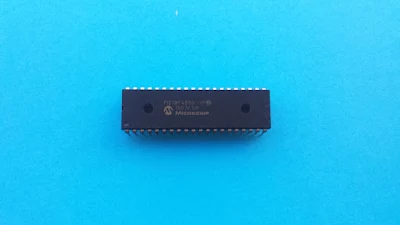
PIC18F4550 is an 8-bit micro-controller from Microchip. In the PIC18 series, it has a built-in USB communication module inside. In prototyping we usually built the circuit on a bread board with some jumper wire. It usually cause damage to the device when we wrongly connect the circuit.
 |
| PIC18F4550 in DIP package I posses. |
Using a per-soldered board most of prototyping is safer and more reliable. Some ready made learning board could be found on E bay or Amazon below 10 US Dollars.
PCB Project Design And Make
However, we can build our own learning board at home using a dozen of existing components. I made a simple learning board by myself at free time. The design fits any 40-pin 8-bit PIC device. But I tend to use PIC18F4550 with a USB type-B connector on board.
 |
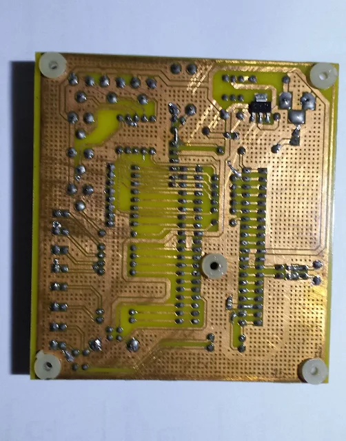
| Bottom side |
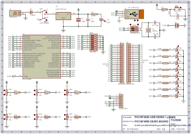
These are some building block of the board:
- A +12 V to +5 V DC regulated power supply
- A soldered crystal clock and reset circuit
- A 6-pin ICSP connector for downloading the program
- A USB type-B connector
- A DIP switch connected to PORTB
- An 8-bit LED connected to PORTD
- Six POTs connected to analog input pins RA0 to RA5
I have already test the functionalities of this board and it's fully worked.
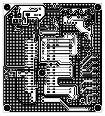
The overall schematic and PCB design are made using Proteus 8.
 |
| Copper Side |
PIC18F4550 Tutorials In CCS PICC
- Start To Blink PIC18F4550 Using CCS PICC
- PIC18F4550 Basic ADC Programming In CCS PICC
- LED Bar Graph Voltage Level Indicator With PIC18F4550
- PIC18F4550 LCD Interfacing in CCS PICC
- PIC18F4550 ADC Reading And LCD Displaying With CCS PICC
- PIC18F4550 interfaces to LM35 and LCD
- CCS PICC basic PWM example with PIC18F4550
- A simple DIY DC voltmeter with PIC18F4550
- PIC18F4550 interfaces to DS1307 RTC and character LCD
- Interfacing PIC18F4550 to 74HC595 CCS PICC


No comments:
Post a Comment