In this post, I use PIC18F4550 to read two analog input channels. A character LCD as used in the previous post displays the value of ADC reading of each channel and its analog voltage value. However, here I use the full 10-bit ADC resolution of this device.
00:00 / 00:00
![]() |
ADC reading and its value displaying |
Source code from GitHub gist:
This file contains bidirectional Unicode text that may be interpreted or compiled differently than what appears below. To review, open the file in an editor that reveals hidden Unicode characters.
Learn more about bidirectional Unicode characters
#include<18f4550.h> | |
#device ADC=10 | |
/*Use high speed clock no PLL prescaler | |
no system clock post scaler */ | |
#fuses HS,PLL1,CPUDIV1 | |
#use delay(clock=20M) | |
#define LCD_ENABLE_PIN PIN_B2 | |
#define LCD_RS_PIN PIN_B0 | |
#define LCD_RW_PIN PIN_B1 | |
#define LCD_DATA4 PIN_B4 | |
#define LCD_DATA5 PIN_B5 | |
#define LCD_DATA6 PIN_B6 | |
#define LCD_DATA7 PIN_B7 | |
#include<lcd.c> | |
void adcConfig(void){ | |
//RA0 AND RA1 As Input | |
set_tris_a(0x03); | |
//PORTD as output | |
set_tris_d(0x00); | |
//Set RA0 To Analog | |
setup_adc_ports(AN0_TO_AN1); | |
//Select ADC internal RC Clock | |
setup_adc(ADC_CLOCK_INTERNAL); | |
} | |
int16 getAnalog(char channel){ | |
set_adc_channel(channel); | |
delay_ms(1); | |
int16 analogValue=read_adc(); | |
while(!adc_done()); | |
return analogValue; | |
} | |
void main(){ | |
float voltage; | |
int16 adcValue; | |
lcd_init(); | |
adcConfig(); | |
while(1){ | |
lcd_gotoxy(1,1); | |
adcValue=getAnalog(0); | |
voltage=(adcValue*5.0)/1024; | |
printf(LCD_PUTC,"AN0: %Lu %.2fV ",adcValue,voltage); | |
lcd_gotoxy(1,2); | |
adcValue=getAnalog(1); | |
voltage=(adcValue*5.0)/1024; | |
printf(LCD_PUTC,"AN1: %Lu %.2fV ",adcValue,voltage); | |
delay_ms(500); | |
} | |
} |
Click here to download zip file of this example.
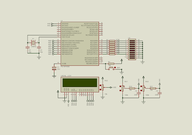
![]() |
Schematic Diagram |
No comments:
Post a Comment