Overview Of DS18B20
DS18B20 is a digital interface temperature sensor from Maxim Integrated. It has only one wire digital data input output, with two additional supply voltage pins. The temperature conversion from this device ranges from -55 degree Celsius to +125 degree Celsius.
Digital temperature resolution is select-able between 9 to 12-bit. Within these 12-bit digital data, it consists of signed value, decimal temperature value and a 4-bit fraction numbers.
 |
| A temperature reading from DS18B20 strobe-type. |
Using only one wire digital data line, we can use multiple devices on this single wire. Each device is identified by its serial number and family code.
 |
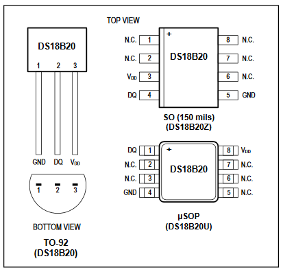
| The conventional package and pin diagram of DS18B20 |
Within three pins of this device, the data DQ pin is open-drain. Hence it needed to pull up high via a resistor about 4.7 kOhm of resistance.
 |
| Typical connection to MCU |
In some case, it doesn't require VDD.
Arduino Interfaces To DS18B20 With OneWire Library
Using the OneWire library developed by an author on Github, reading the device ID and temperature from this device family save a lot of time.
This library allow us to search for ROM. ROM identifies the devices connect on one wire bus. So we can use as much as one wire devices on a single line.
There are many function that I don't list them here. The example programs come this device could explain a lot about the overall processes.
In this example, I modified the device search and temperature reading to display their information on a SPI character LCD I made.
 |
| Schematic Diagram For This Example |
Arduino code lists below.
#include <OneWire.h>
#include <ShiftedLCD.h>
#include <SPI.h>
//OneWire Object Connect To Pin 2
OneWire ds(2);
//Select pin 8 for Enable pin
LiquidCrystal lcd(8);
String dsString="";
void setup(void) {
Serial.begin(9600);
lcd.begin(16,4);
lcd.clear();
}
void loop(void) {
byte i;
byte present = 0;
byte type_s;
byte data[12];
byte addr[8];
float celsius, fahrenheit;
if ( !ds.search(addr)) {
ds.reset_search();
delay(250);
return;
}
if (OneWire::crc8(addr, 7) != addr[7]) {
return;
}
// the first ROM byte indicates which chip
switch (addr[0]) {
case 0x10:
type_s = 1;
dsString="DS18S20";
break;
case 0x28:
dsString="DS18B20";
type_s = 0;
break;
case 0x22:
dsString="DS1820";
type_s = 0;
break;
default:
dsString="N/A";
return;
}
lcd.setCursor(0,0);
lcd.print("Sensor: "+dsString);
ds.reset();
ds.select(addr);
ds.write(0x44, 1); // start conversion, with parasite power on at the end
delay(1000); // maybe 750ms is enough, maybe not
// we might do a ds.depower() here, but the reset will take care of it.
present = ds.reset();
ds.select(addr);
ds.write(0xBE); // Read Scratchpad
// Convert the data to actual temperature
// because the result is a 16 bit signed integer, it should
// be stored to an "int16_t" type, which is always 16 bits
// even when compiled on a 32 bit processor.
int16_t raw = (data[1] << 8) | data[0];
if (type_s) {
raw = raw << 3; // 9 bit resolution default
if (data[7] == 0x10) {
// "count remain" gives full 12 bit resolution
raw = (raw & 0xFFF0) + 12 - data[6];
}
} else {
byte cfg = (data[4] & 0x60);
// at lower res, the low bits are undefined, so let's zero them
if (cfg == 0x00) raw = raw & ~7; // 9 bit resolution, 93.75 ms
else if (cfg == 0x20) raw = raw & ~3; // 10 bit res, 187.5 ms
else if (cfg == 0x40) raw = raw & ~1; // 11 bit res, 375 ms
//// default is 12 bit resolution, 750 ms conversion time
}
celsius = (float)raw / 16.0;
fahrenheit = celsius * 1.8 + 32.0;
lcd.setCursor(0,1);
lcd.print("Temperature:");
lcd.setCursor(-4,2);
//lcd.print(String(celsius)+char(223)+"C" +" " + String(fahrenheit)+char(223)+"C");
lcd.print(String(celsius)+char(223)+"C");
lcd.setCursor(-4,3);
lcd.print(String(fahrenheit)+char(223)+"F");
delay(1000);
}
Arduino sketch could download here.

No comments:
Post a Comment