Learn To Write Code For 8051, Arduino, AVR, dsPIC, PIC, STM32 ARM Microcontroller, etc.
Coding Embedded Controller With C/C++.
Printed Circuit Board (PCB) Project For Electronics Hobbyists.
A character LCD traditional built with a controller inside especially the HD44780. It's easy to control with some basic LCD instruction. For more technical details and programming interface for this type of LCD controller click here to view. Character LCD are available from as single to multiple lines and multiple characters.
x2
x1.5
x1
x0.5
00:00 / 00:00
Pause
Unmute
Fullscreen
Fluid Player 3.51.0
A running Program
In CCS PIC an LCD software driver is ready to use in side the compiler. The LCD.C driver could control a character LCD only for two line character LCD. Within this driver there are a lot of functions lists below.
lcd_init() - must be called before calling other function
lcd_putc() - send one character to LCD
lcd_gotoxy(x,y) - set write position on LCD, start from 1,1
lcd_getc(x,y) - return character at the position x,y on LCD
lcd_cursor_on(int1 on) - turn on cursor
lcd_set_cgram_char(w,*p) - write custom character to CGRAM
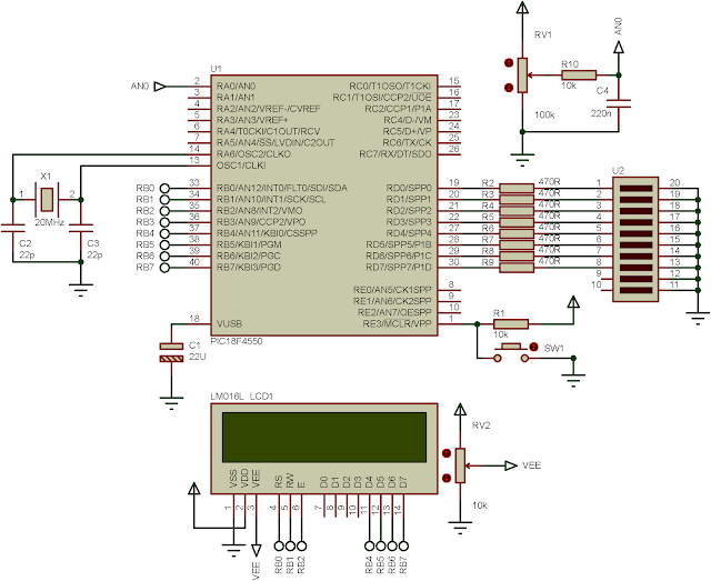
In this example, the LCD prints the duration of MCU started up time. The C printf function could be use to send the character to LCD by adding the LCD_PUTC stream to this function.
This file contains bidirectional Unicode text that may be interpreted or compiled differently than what appears below. To review, open the file in an editor that reveals hidden Unicode characters.
Learn more about bidirectional Unicode characters
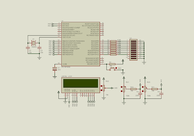
In this post, I use PIC18F4550 to read two analog input channels. A character LCD as used in the previous post displays the value of ADC reading of each channel and its analog voltage value. However, here I use the full 10-bit ADC resolution of this device.
ADC reading and its value displaying
Source code from GitHub gist:
This file contains bidirectional Unicode text that may be interpreted or compiled differently than what appears below. To review, open the file in an editor that reveals hidden Unicode characters.
Learn more about bidirectional Unicode characters
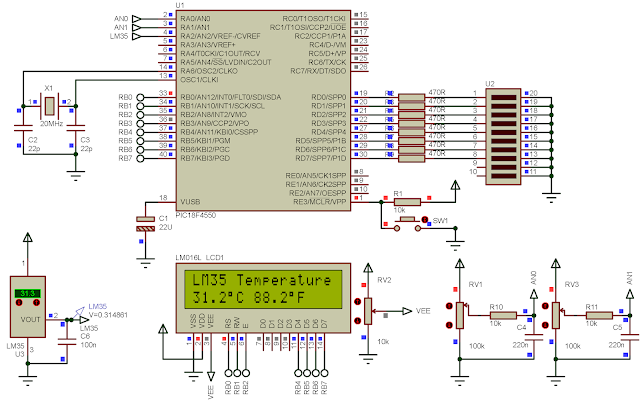
Referring to ADC module of PIC18F4550, there are many analog output sensor to interfaces with this MCU. LM35 is a simple analog temperature sensor, creating analog voltage output representing its temperature conversion in degree Celsius. The step temperature from this device is 10 mV per degree Celsius. I don't want to put all its details here. For more information about using this device, please see this post.
In this post, LM35 connects to AN2 analog channel of the ADC. The MCU reads the analog voltage, converting it to temperature value in both degree Celsius and degree Fahrenheit.
A temperature reading of 31.2 degree Celsius.
A very simple LM35 comes in a transistor-like TO-92 package.
LM35DZ in TO-92 package.
C source code fed from GitHub.
This file contains bidirectional Unicode text that may be interpreted or compiled differently than what appears below. To review, open the file in an editor that reveals hidden Unicode characters.
Learn more about bidirectional Unicode characters
Creating a varied analog voltage output from an MCU require an analog voltage generator, PWM (pulse width modulation). Making a analog voltage PWM to work, the user needs to know about all relevant register configurations to set the frequency and duty cycle of PWM signal.
However, in a high level embedded language, creating a PWM signal output doesn't need a deep level of low level hardware/register configuration. With a few C functions, the PWM signal output from any MCU could be created in a few minutes.
CCS PICC Basic Pulse Width Modulation Programming
Without using any technical detail of PWM software setting, we can create a PWM output from scratch with this compiler. In this introductory example, I use only a few C code to program the PWM.
#use PWM directive
pwm_set_duty_percent()
The directive #use PWM has many options, but I list a few commonly use options of this.
CCPx or PWMx - Select a CCP/PWM module
FREQUENCY=x - Set the frequency of PWM signal
PERIOD=x - Set the period of PWM signal
DUTY=x - The default duty cycle is 50% if it's not set.
For more details about this directive, check the compiler manual.
The pwm_set_duty_percent specifies the duty cycle of PWM output signal. The syntax is pwm_set_duty_percent(stream,value). Where stream is optional, and value is ranges from 0 to 1000. For example when value = 500, the PWM duty cycle is 50% and so on.
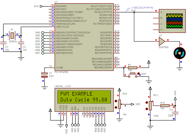
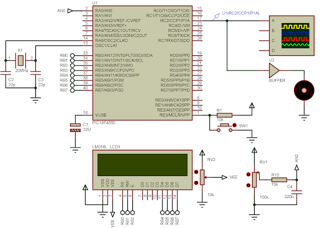
In this introductory example, I set a fixed frequency of PWM and a variable duty cycle. Duty cycle is adjusted by the variation of a POT. CCP1 is selected to make the PWM signal.
I adjust the POT to the MAX.
C Source Code
This file contains bidirectional Unicode text that may be interpreted or compiled differently than what appears below. To review, open the file in an editor that reveals hidden Unicode characters.
Learn more about bidirectional Unicode characters
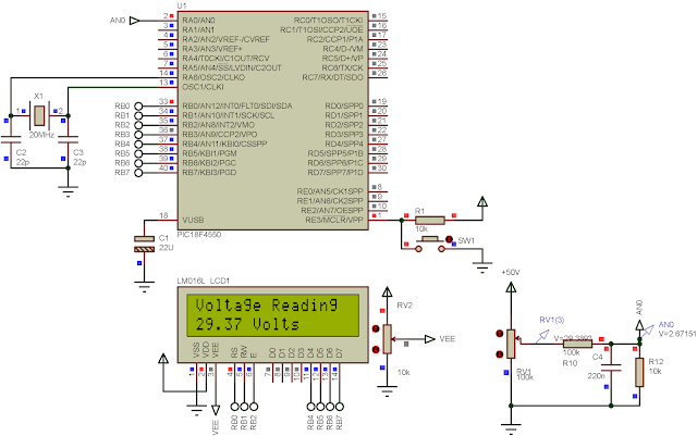
The ADC module of PIC18F4550 could read an analog input voltage up to 5 V DC with some DC offset. However, the outside analog voltage fed to the ADC could be greater than 5 V DC by adding a simple voltage divider circuit.
The voltage divider circuit is very simple, built by two resistors in this case. The output voltage from the divider circuit is smaller than the input according to the dividing factor. The factor created by picking up a different resistances of the selected's. The designer may decide and take a little math calculation using voltage divider theorem to get a specific division factor.
The MCU reads the analog input voltage fed to RA0.
PICC Source Code
This file contains bidirectional Unicode text that may be interpreted or compiled differently than what appears below. To review, open the file in an editor that reveals hidden Unicode characters.
Learn more about bidirectional Unicode characters
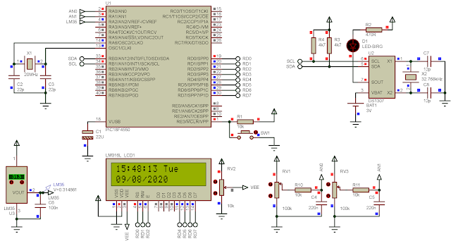
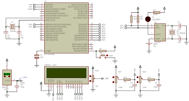
PIC18F4550 has a master synchronous serial ports (MSSP) module inside. This module consist of two sub-communication modules - I2C and SPI. An I2C is communication protocol for short range, low data rate requires only two pins - Serial Data(SDA) and Serial Clock(SCL). However, the SPI communication port doesn't lists here.
DS1307 is a real time clock keeper with I2C communication interface. This device keep the time running by an external crystal clock of 32.768 kHz. Even the supply voltage is off, a coin back up battery keep the data RAM synchronizes for future use. Since an I2C is use for communication, there are two communication pins - SDA and SCL. These two pins are open drain, require an individual external pull up resistor. The resistor ranges from 4.7 kOhm to 10 kOhm resistance.
In this programming example, PIC18F4550 uses its I2C master to write and read timing data from DS1307 I2C slave device. Those data will display on a character display.
Circuit Simulation
PICC Source Code
This file contains bidirectional Unicode text that may be interpreted or compiled differently than what appears below. To review, open the file in an editor that reveals hidden Unicode characters.
Learn more about bidirectional Unicode characters
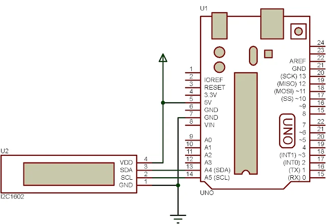
A character LCD with a 44780 LCD controller generally controlled by an MCU parallel port. Even the data transfer in-used is 4-bit mode, but it still require up to six MCU pins.
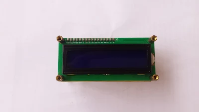
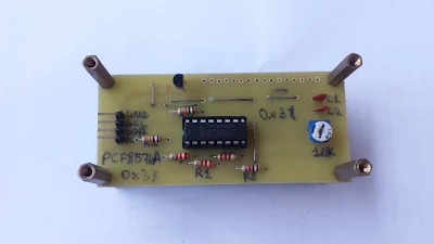
In online market the PCF8574AP is built in module the a character LCD that cost a few Dollars. For an electronics hobbyist like me, I only bought a single DIP version of this chip. I can program it to read/write digital data before I decide to put it with a character LCD.
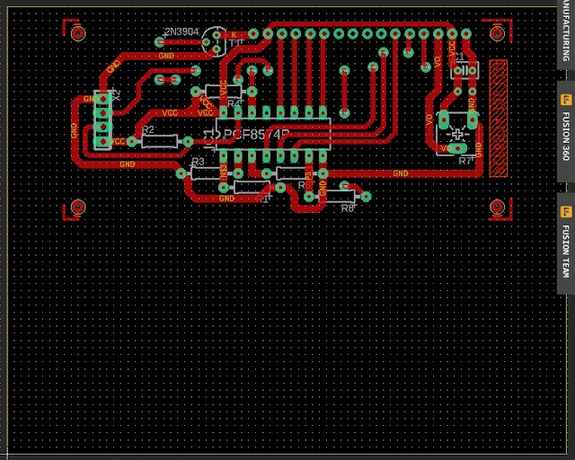
I decided to make my own I2C board module for my Arduino Uno board. This design follows the liquidCrystal_I2C LCD library from an author on GitHub. The overall design is not difference from the original one's but I made my own schematic and PCB design for my personal use.
I use Eagle CAD from Auto Desk software due to its richness of symbols and footprints library. The result yield with a small rectangular PCB module wired with PCF8574AP and a character LCD.
Schematic Diagram
PCB View
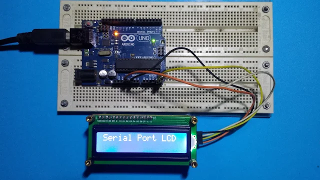
This design example is fully worked as I have tested it with Arduino Uno using its library.
This Arduino sketch is from the library itself with some of my own modification.
#include <Wire.h> #include <LiquidCrystal_I2C.h>
// set the LCD address to 0x38 for PCF8574A with A0 A1 A2 wired to GND LiquidCrystal_I2C lcd(0x38,16,2); void setup() { // initialize the lcd lcd.init(); lcd.backlight(); lcd.clear(); Serial.begin(9600); lcd.setCursor(0,0); lcd.print("Serial Port LCD"); }
void loop() { // when characters arrive over the serial port... if (Serial.available()) { // wait a bit for the entire message to arrive delay(100); // clear the screen lcd.clear(); // read all the available characters while (Serial.available() > 0) { // display each character to the LCD lcd.write(Serial.read()); } } }