Overview
With in the TWI module of Atmega32 MCU, I have already post about interfacing and programming with the DS1307 RTC. However, in the previous post, the display interface was a simple multiplexed 7-segment display. Here, the display is an HD44780-based character LCD.
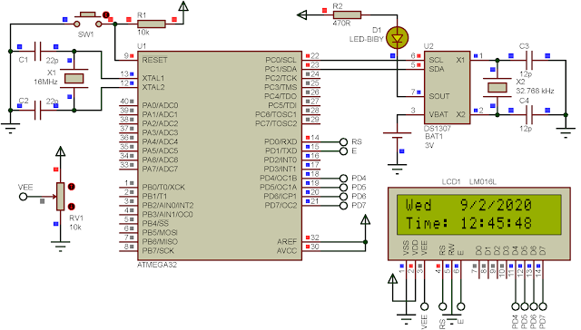
In this example post, the program read the date/time and day of week from the RTC. Those data will display on a character LCD for every one second.
00:00 / 00:00
![]() |
A running example program |
DS1307 RTC Interfacing And Programming With ATMega32 AVR
DS1307 has a writing address of 0xD0 while the writing address is 0xD1. Its RAM registers store time, date, configuration register and general purpose SRAM registers. The RAM address of 0x00 is the second register and so on. This post store some information about the DS1307.
![]() |
Schematic |
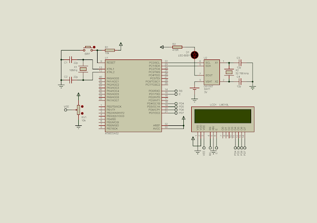
PORTD interfaces to the character LCD. PC0 and PC1 are the TWI clock and data pins, respectively. As we can see, the DS1307 TWI device doesn't need its two pull up resistors. Setting PC0 and PC1 high by software eliminates the requirement of external resistors.
This file contains bidirectional Unicode text that may be interpreted or compiled differently than what appears below. To review, open the file in an editor that reveals hidden Unicode characters.
Learn more about bidirectional Unicode characters
/* | |
* ds1307Lcd.c | |
* | |
* Created: 9/1/2020 9:47:37 PM | |
* Author : aki-technical | |
*/ | |
#include <avr/io.h> | |
#include <stdio.h> | |
#define F_CPU 16000000UL | |
#include <util/delay.h> | |
#define lcdPort PORTD | |
#define lcdDir DDRD | |
#define RS 0 | |
#define E 1 | |
void lcdPortInit(void){ | |
//Only PORTD Is LCD Port | |
lcdDir=0xFF; | |
//Turn On PC0 And PC1 | |
PORTC=0x03; | |
} | |
void writeCommand(char command){ | |
lcdPort=(command&0xF0)|(1<<E); | |
lcdPort=(command&0xF0); | |
_delay_us(50); | |
lcdPort=(command<<4)|(1<<E); | |
lcdPort=(command<<4); | |
_delay_ms(3); | |
} | |
void writeChararacter(char character){ | |
lcdPort=(character&0xF0)|(1<<E)|(1<<RS); | |
lcdPort=(character&0xF0)|(1<<RS); | |
_delay_us(50); | |
lcdPort=(character<<4)|(1<<E)|(1<<RS); | |
lcdPort=(character<<4)|(1<<RS); | |
_delay_ms(3); | |
} | |
void writeString(char *text){ | |
while(*text) writeChararacter(*text++); | |
} | |
/*This function ease of setting the cursor position*/ | |
void setXy(int x,int y){ | |
/*Select A 40x4 LCD*/ | |
char numberOfLines[4]={0x80,0xC0,0x94,0xD4}; | |
/* The position starts from (x,y)=(0,0) */ | |
writeCommand(numberOfLines[x]+y); | |
} | |
void lcdInit(void){ | |
/*Initialize the LCD PORT*/ | |
lcdPortInit(); | |
/*Writing the instructions | |
4-bit mode, 2-line,5x8 dot*/ | |
writeCommand(0b00110011); | |
writeCommand(0b00110010); | |
writeCommand(0b00101000); | |
writeCommand(0x01); | |
/*Turn On Display, Cursor Off*/ | |
writeCommand(0b00001100); | |
/*Cursor Shift in Increment Mode*/ | |
writeCommand(0b00000110); | |
} | |
void i2cInit(void){ | |
TWSR=0x03; //Bit Rate Pre-scaler Is 1:64 | |
TWBR=0x0F; | |
TWCR=(1<<TWEN); //Enable The TWI Module | |
PORTC|=(1<<0); | |
PORTC|=(1<<1); | |
} | |
void i2cStart(void){ | |
TWCR=(1<<TWINT)|(1<<TWSTA)|(1<<TWEN); | |
while((TWCR&(1<<TWINT))==0); | |
} | |
void i2cWrite(unsigned char data){ | |
TWDR=data; | |
TWCR=(1<<TWINT)|(1<<TWEN); | |
while((TWCR&(1<<TWINT))==0); | |
} | |
unsigned char i2cRead(char ACK){ | |
if(ACK==0) | |
TWCR=(1<<TWINT)|(1<<TWEN)|(1<<TWEA); | |
else | |
TWCR=(1<<TWINT)|(1<<TWEN); | |
while((TWCR&(1<<TWINT))==0); | |
return TWDR; | |
} | |
void i2cStop(){ | |
TWCR=(1<<TWINT)|(1<<TWEN)|(1<<TWSTO); | |
} | |
void ds1307Init(void){ | |
i2cStart(); | |
/*D0 is DS1307 Write Address*/ | |
i2cWrite(0xD0); | |
/*Select Control Register*/ | |
i2cWrite(0x07); | |
/*Enable SQWE bit blinks at 1 Hz*/ | |
i2cWrite(1<<4); | |
i2cStop(); | |
} | |
int main(void) | |
{ | |
char times[7],timeString[16],dateString[16]; | |
char *dayOfWeek; | |
lcdInit(); | |
i2cInit(); | |
ds1307Init(); | |
while (1) { | |
/*Second Register*/ | |
i2cStart(); | |
i2cWrite(0xD0); | |
/*Select Second register*/ | |
i2cWrite(0x00); | |
i2cStop(); | |
for(int i=0;i<7;i++){ | |
i2cStart(); | |
i2cWrite(0xD1); | |
times[i]=i2cRead(1); | |
i2cStop(); | |
} | |
/*Find Day Of Week String*/ | |
switch(times[3]){ | |
case 1: dayOfWeek="Sun"; break; | |
case 2: dayOfWeek="Mon"; break; | |
case 3: dayOfWeek="Tue"; break; | |
case 4: dayOfWeek="Wed"; break; | |
case 5: dayOfWeek="Thu"; break; | |
case 6: dayOfWeek="Fri"; break; | |
case 7: dayOfWeek="Sat"; break; | |
default: dayOfWeek=""; break; | |
} | |
/*Make Day Of Week Month Day And Year String*/ | |
sprintf(dateString,"%s %x/%x/20%x ",dayOfWeek,times[5],times[4],times[6]); | |
setXy(0,0); | |
/*Displaying The Date*/ | |
writeString(dateString); | |
/*Make Time: Hour:Minute:Second String*/ | |
sprintf(timeString,"Time: %x:%x:%x ",times[2],times[1],times[0]); | |
setXy(1,0); | |
/*Displaying The Time*/ | |
writeString(timeString); | |
/*Waiting For Next Second*/ | |
_delay_ms(1000); | |
} | |
} |
Click here to download the archive of this example.
For more tutorial on HD44780 character LCD:
No comments:
Post a Comment