Overview of AVR TWI Module
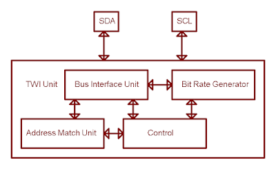
In AVR microcontroller the I2C module is referred as Two-wire Serial Interfaces. This TWI module made of many sub-modules.
 |
| A short block diagram of TWI module |
SDA and SCL Pins
SDA and SCL pins are outside connection pin, connect to any TWI devices. In most microcontrollers, these two pins are open-drain, require individual pull up resistor with the resistance between 4.7 kOhm to 10 kOhm. However, in ATMega32 this two pin could be internally pull up without using that two external resistors. It's done by setting them to high in software.
Bit Rate Generator
In master mode, this unit control the period of SCL. CPU frequency and TWBR effect the frequency of SCL.
Where,
- TWBR - Value of the TWI Bit Rate Register
- TWPS - Value of the prescaler bits
Other details about remaining sub-module list above could not list here as all detailed in its datasheet. For a summary of I2C or TWI, click here to view.
TWI Registers
Configuring the TWI
Initialize the Master TWI module
- Set an appropriate value of SCL frequency by working with the prescaler (TWPS) in TWSR and the bit rate selection TWBR in of the the TWCR register.
- Optionally, set the SCL and SDA pin high to eliminate the requirement of two external weak pull up resistors.
- Turn on the TWI module by setting the the TWEN of the TWCR to '1'.
Make the START condition
- Set the interrupt flag TWINT, START condition TWSTA, enable the module TWEN
- Waiting for TWINT is cleared.
Writing to the slave device
- Put data into the TWDR register
- Set the interrupt flag and enable the module
- Waiting for the interrupt flag is cleared
Reading from the slave device
- Enable or disable the ACK bit
- Waiting for the interrupt flag is cleared
- Read data from the TWDR register
Stop the transmision
- Set the interrupt flag
- Enable the module
- Set the STOP bit TWSTO to 1
An example of SCL frequency calculation:
TWI Programming In Atmel Studio
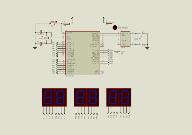
In this example I interface the master AVR to DS1307 slave TWI device. This chip is a real time clock.
For this slave device, the writing address is 0xD0 and the reading address is 0xD1. The timing register starts from 0x00, second register and so on. The control register configures the square wave output from SOUT pin with varies frequency.
To write to this device, address 0xD0 is written first, after that the address we wish to write and finally the data that will be load to that address.
To read to this device, address 0xD1 is written first, after that the address we wish to read and finally issue a reading from that address.
 |
| A schematic of this example |
Atmel Studio C source code:
/*
* i2c_example_1_ds1307.c
*
* Created: 7/27/2020 7:11:43 PM
* Author : admin
*/
#include <avr/io.h>
#define F_CPU 4000000UL
#include <util/delay.h>
void i2cInit(void){
TWSR=0x03; //Bit Rate Pre-scaler Is 1:64
TWBR=0x0F; //SCL Frequency Is 1.9kHz at 5MHz
TWCR=(1<<TWEN); //Enable The TWI Module
PORTC|=(1<<0);
PORTC|=(1<<1);
}
void i2cStart(void){
TWCR=(1<<TWINT)|(1<<TWSTA)|(1<<TWEN);
while((TWCR&(1<<TWINT))==0);
}
void i2cWrite(unsigned char data){
TWDR=data;
TWCR=(1<<TWINT)|(1<<TWEN);
while((TWCR&(1<<TWINT))==0);
}
unsigned char i2cRead(char ACK){
if(ACK==0)
TWCR=(1<<TWINT)|(1<<TWEN)|(1<<TWEA);
else
TWCR=(1<<TWINT)|(1<<TWEN);
while((TWCR&(1<<TWINT))==0);
return TWDR;
}
void i2cStop(){
TWCR=(1<<TWINT)|(1<<TWEN)|(1<<TWSTO);
}
int main(void)
{
DDRA=0xFF;
DDRB=0xFF;
DDRD=0xFF;
i2cInit();
i2cStart();
/*D0 is DS1307 Write Address*/
i2cWrite(0xD0);
/*Select Control Register*/
i2cWrite(0x07);
/*Enable SQWE bit blinks at 1 Hz*/
i2cWrite(1<<4);
i2cStop();
while (1)
{
/*Second Register*/
i2cStart();
i2cWrite(0xD0);
/*Select Second register*/
i2cWrite(0x00);
i2cStop();
i2cStart();
i2cWrite(0xD1);
PORTA=i2cRead(1);
i2cStop();
/*Minute Register*/
i2cStart();
i2cWrite(0xD0);
/*Select Second register*/
i2cWrite(0x01);
i2cStop();
i2cStart();
i2cWrite(0xD1);
PORTB=i2cRead(1);
i2cStop();
/*Hour Register*/
i2cStart();
i2cWrite(0xD0);
/*Select Second register*/
i2cWrite(0x02);
i2cStop();
i2cStart();
i2cWrite(0xD1);
PORTD=i2cRead(1);
i2cStop();
_delay_ms(1000);
}
}
 |
| A Sample Of Program |


No comments:
Post a Comment