Thursday, February 8, 2024

PIC16F887 Serial Peripheral Interface Example

Overview

Serial Peripheral Interface (SPI) is a wired synchronous serial communication interface, commonly used in embedded electronics control system used for communication between controller and its peripheral devices. 
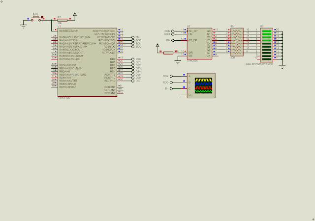
PIC16F887 Serial Peripheral Interface Example
SPI Example with the SN74HC595N Shift Registers Chip

Typical applications include interfacing micro-controllers with peripheral chips for Secure Digital cards, liquid crystal displays, analog-to-digital and digital-to-analog converters, flash and EEPROM memory, and various communication chips.

PIC16F887 Serial Peripheral Interface Example
SPI Master Multiple Slave Devices Diagram
One SPI master device able to connect to many slave devices. Additional slave device requires one chip select (CS) pin. Conventionally these SPI  defined as follow,

  • SCK - Serial Clock
  • MOSI - Master Out Slave In
  • MISO - Master In Slave Out
  • CS - Chip Select

These symbol commonly used for the AVR micro-controller from Microchip Technology. However the Microchip PIC micro-controllers use different symbols.

PIC16F887 Serial Peripheral Interface (SPI)

The PIC16F887 has a Master Synchronous Serial Port (MSSP) Module that contains the SPI and I2C module. The communication configuration depends on software setting in program.

The SPI pins locate at,

  • RC3 - Serial Clock (SCK)
  • RC4 - Serial Data In (SDI)
  • RC5 - Serial Data Out (SDO)
  • nSS - Slave Select (RA5)

The SPI operation could be configured as master or slave mode.
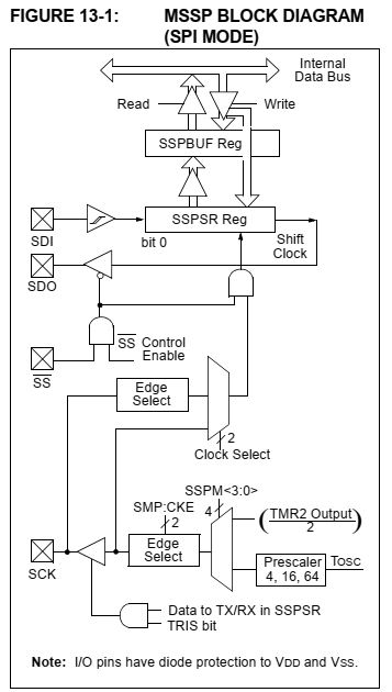
PIC16F887 Serial Peripheral Interface Example
MSSP Block Diagram (SPI Mode)
 

To operate in master mode, the SCK, SDO and SS pin must configured as digital output pins. The SDI pin must be configured as digital input pin. The SPI operation relates to these SFR registers.
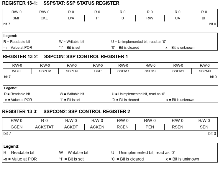
PIC16F887 Serial Peripheral Interface Example
MSSP Registers
For more details about these registers you can read the datasheet of this device.

The SSPBUF is an 8-bit readable/writable register for data transmitting and receiving. The programmer must set the following configuration to operate the SPI master mode.

  • Set serial clock polarity and data sample mode
  • Set the SPI clock frequency
  • Set the SPI I/O pins direction
  • Enable the SPI module

In master mode we can select various SPI wave forms.
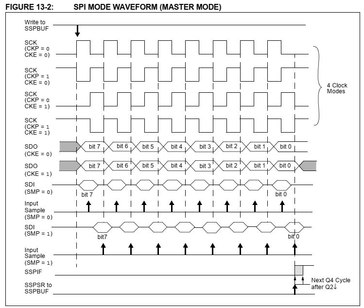
PIC16F887 Serial Peripheral Interface Example
SPI Master Mode Wave Form
The commonly used wave form is a low to high clock transition. The slave select pin used for latching the data into the slave device. It could be a high to low transition, or vice versa depending on the target slave device specification. 

The SN74HC595N Shift Registers Interfacing Example

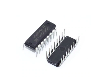
In this example, I use the SN74HC595N serial in parallel out shift registers to interface with the master SPI module of PIC1F887. The SN74HC595N operate as a SPI slave device receiving the data from the master.
PIC16F887 Serial Peripheral Interface Example
SN74HC595N DIP-16

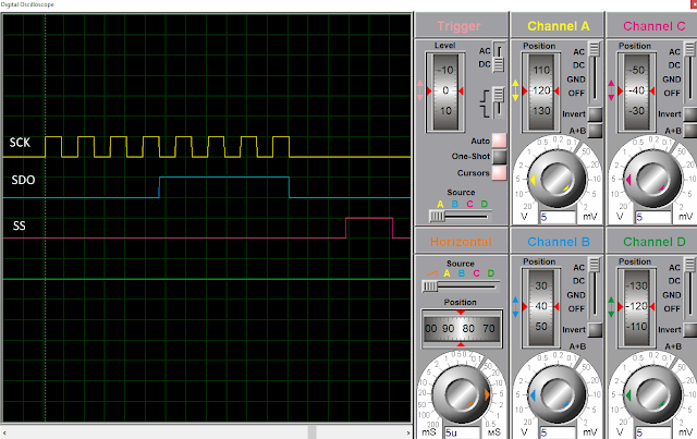
The clock transition is positive edge (low to high). The latch (slave select) pin is a high to low transition.
PIC16F887 Serial Peripheral Interface Example
SPI Wave Form

We can serially connect these chips as much as possible. This chip is very popular in driving seven segment display or dot matrix display.

In this example, the PIC16F887 master SPI will send an 8-bit data to the SN74HC595N periodically. 

  1. /*
  2.  * File: main.c
  3.  * Author: Admin
  4.  *
  5.  * Created on February 6, 2024, 9:16 PM
  6.  */
  7.  
  8. #include <xc.h>
  9. #include "config.h"
  10.  
  11. #define _XTAL_FREQ 8000000UL
  12.  
  13. void spi_init(void){
  14. /*SPI Mode Clock Low To High*/
  15. SSPCONbits.CKP=0;
  16. SSPSTATbits.CKE=1;
  17. SSPSTATbits.SMP=0;
  18. /*SPI Master Mode Clock = Fosc/64*/
  19. SSPCONbits.SSPM=2;
  20. /*Turn On The Module*/
  21. SSPCONbits.SSPEN=1;
  22. SSPSTATbits.BF=1;
  23. }
  24.  
  25. void main(void) {
  26. OSCCONbits.IRCF=7;
  27. spi_init();
  28. PORTC=0;
  29. TRISC=0;
  30. TRISC4=1;
  31. while(1){
  32. SSPBUF=0xF0;
  33. __delay_us(80);
  34. RC2=1;
  35. __delay_us(10);
  36. RC2=0;
  37. __delay_ms(1000);
  38.  
  39. SSPBUF=0x0F;
  40. __delay_us(80);
  41. RC2=1;
  42. __delay_us(10);
  43. RC2=0;
  44. __delay_ms(1000);
  45.  
  46. SSPBUF=0xAA;
  47. __delay_us(80);
  48. RC2=1;
  49. __delay_us(10);
  50. RC2=0;
  51. __delay_ms(1000);
  52. }
  53. return;
  54. }
  55.  

Click here to download this example.


No comments:

Post a Comment

Search This Blog

Labels

25AA010A (1) 8051 (7) 93AA46B (1) ADC (30) Analog Comparator (1) Arduino (15) ARM (6) AT89C52 (7) ATMega32 (56) AVR (57) CCS PICC (28) DAC (1) DHT11 (2) Display (105) Distance Sensor (3) DS18B20 (3) dsPIC (2) dsPIC30F1010 (2) EEPROM (5) Environment Sensor (4) esp8266 (1) I2C (29) Input/Output (67) Interrupt (19) Keil (5) Keypad (10) LCD (47) Master/Slave (1) MAX7221 (1) MCP23017 (5) MCP23S17 (4) Meter (3) MikroC (2) Motor (15) MPLABX (71) Nokia 5110 LCD (3) OLED (2) One-Wire (6) Oscillator (8) PCB (6) PCD8544 (3) PCF8574 (5) PIC (107) PIC12F (2) PIC16F628A (2) PIC16F630 (1) PIC16F716 (3) PIC16F818 (10) PIC16F818/819 (2) PIC16F84A (15) PIC16F876A (1) PIC16F877A (9) PIC16F88 (1) PIC16F887 (60) PIC18 (19) PIC18F1220 (4) PIC18F2550 (3) PIC18F4550 (12) PWM (11) RTC (8) Sensor (10) SH1106 (1) Shift Register (11) Shift Registers (3) SPI (24) STM32 (6) STM32 Blue Pill (6) STM32CubeIDE (6) STM32F103C8T6 (6) SysTick (3) temperature sensor (11) Thermometer (21) Timer/Counter (31) TM1637 (2) UART (7) Ultrasonic (4) Voltmeter (7) WDT (1) XC16 (2) XC8 (94)