Introduction
In microcontroller, interrupt is hardware or software event notification to the system. Each time interrupt occurs the system could respond or ignore to that event. Amount of interrupt capabilities of microcontroller is different. Interrupt triggered by internal or external events.
 |
| Simulation Sample of this programming example |
PIC16F818 has many interrupt sources that we can not list them all here. External interrupt is an interrupt source triggered by external logic change on pin RB0 of port B in PIC16F818/819. It can be an interrupt on falling or rising edge depends on user configuration in software.
External Interrupt Preparation
There are many steps of software configuration in programming. We will need to configure port data direction, interrupt edge, global interrupt control, etc.
Port Data Direction
Pin RB0 must be a digital input as it’s a logic input to the microcontroller. An optional weak pull-up resistor could save the number of external add-on components and circuit wiring. Hence the user must clear nRBPU of the OPTION register.
 |
| OPTION Register |
But the interrupt edge must selected to work in falling edge of input logic.
Interrupt Edge Selection
Edge of external interrupt are rising and falling edge. The user select between these two mode using Interrupt Edge Select Bit (INTEDG) of the OPTION register.
 |
| Interrupt Edge Select Bit |
Clearing this bit to select the interrupt on falling edge from external input device – for example a motion sensor.
Turning on External Interrupt
Interrupt Control Register (INTCON) consists of many interrupt source setting and interrupt flag, including the external interrupt. An interrupt flag in PIC microcontroller is set whenever the corresponding interrupt source occurs. The user must test and clear this flag in software at the time it occurs and ended.
 |
| Interrupt Control Register (INTCON) |
Bit 7 of INTCON is a Global Interrupt Enable bit (GIE) is a general interrupt switch. Setting to ‘1’ before other interrupt sources are enabled.
Bit 4 is an External Interrupt Enable bit (INTE). Setting this bit to turn on external interrupt on RB0.
Bit 1 is an External Interrupt Flag bit (INTF). This bit must be cleared first in the first program configuration for the external interrupt. In the Interrupt Service Routine (ISR), the code must test this bit to find its occurrence.
Interrupt Service Routine
An Interrupt Service Routine (ISR) is a piece of code written in the interrupt vector of PIC microcontroller. It responses to the interrupt whenever it’s enabled an occured.
In mid-range PIC microcontroller as PIC16F818 there is only one interrupt vector locates at the address 0x04 in program memory. However in a high level programming language like XC8 we don’t care about this vector. ISR in XC8 is just a C function but it’s reserved for interrupt vector.
void interrupt _ISR_NAME(void){
//Code here
}
In ISR the user must test the interrupt flag, writing codes to response to interrupt, and clear interrupt flag.
XC8 Programming for External Interrupt
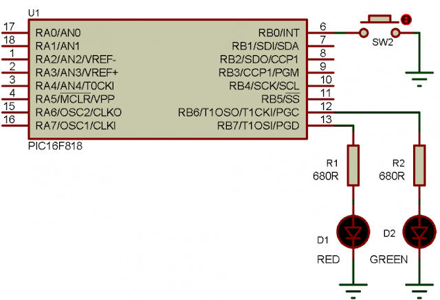
This simple external interrupt programming example show a blinking LED as its normal main program routine. Whenever the external interrupt occurs, it toggles an output LED.
Schematic Diagram
External interrupt attaches to RB0 while two output LED are the main program loop blinking and another LED is interrupt response.
 |
| Schematic diagram for this interrupt programming example |
SW2 triggers the external interrupt at whenever it’s pressed.
XC8 Programming
Software setting configure this controller to use its internal oscillator clocks at 4MHz. Other remaining code are written to support the interrupt capabilities.
Click here to download this example archive.
No comments:
Post a Comment