Introduction
As it’s discussed in previous post, Timer0 of PIC microcontroller is able to trigger an interrupt signal every time its timer register overflows and reset to its initial value of 0.
Programming for Timer0 interrupt is just like other interrupt programming for PIC microcontroller in MPLABX XC8. The programmer is required to enable its global interrupt switch, Timer0 interrupt enable bit, writing an interrupt service routine, etc.
Timer0 Interrupt Programming
We have discussed a lot in previous post about a preparation for interrupt in XC8 programming. Special function registers relate to this interrupt are already shown in these posts.
More About Related Registers
Option register (OPTION_REG) is in used for selecting clock source, timer mode and its clock prescaler.
 |
| OPTION Register – OPTION_REG |
Interrupt Control Register (INTCON) contain some fundamental interrupt control bits and flags.
 |
| Interrupt Control Register – INTCON |
Set Global Interrupt Enable (GIE) bit to enable interrupt for any interrupt source.
Timer0 Overflow Interrupt Enable (TMR0IE) bit must be set to turn on timer 0 interrupt capability.
Timer0 Overflow Interrupt Flag (TMR0IF) bit functions as a testing flag to find the present of timer 0 overflow interrupt occurrence. Initially the program must clear this flag and Timer0 register (TMR0) in software.
Circuit Diagram for Hooking Up and Simulation
The system is prepared to utilize an external crystal oscillator with its maximum frequency of 20MHz. It’s optionally have a reset circuit as usual micro-controllers have. We can ignore this reset circuit in configuration section in source code as it was done in previous post.
 |
| Circuit diagram for both physical hardware prototyping and software simulation |
XC8 Programming
Since the system clock is 20MHz we will need to find all related timing parameters to predict the interrupt interval.
Instruction executing speed is a quarter of microcontroller clock source. So the microcontroller speed is,
FOSC = (20MHz/4) = 5MHz or 5MIPS.
Instruction executing frequency is.
(1/5MHz) = 0.2us.
Timer0 prescaler is 1:256 then Timer0 input clock rate is,
(256*0.2us)= 51.2us.
Timer0 overflow interrupt occurs for every,
(256*51.2us) = 13.1ms.
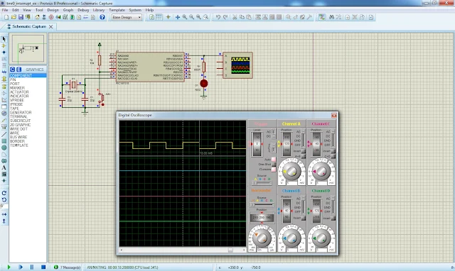
Finally for every 13.1ms, RB0 of PIC16F818 changes its output logic state.
* PIC16F818 Timer0 Interrupt
* Programming Example
*/
#include <xc.h>
// PIC16F818 Configuration Bit Settings
// CONFIG
#pragma config FOSC = HS // Oscillator Selection bits (HS oscillator)
#pragma config WDTE = OFF // Watchdog Timer Enable bit (WDT disabled)
#pragma config PWRTE = OFF // Power-up Timer Enable bit (PWRT disabled)
#pragma config MCLRE = ON // RA5/MCLR/VPP Pin Function Select bit (RA5/MCLR/VPP pin function is MCLR)
#pragma config BOREN = ON // Brown-out Reset Enable bit (BOR enabled)
#pragma config LVP = ON // Low-Voltage Programming Enable bit (RB3/PGM pin has PGM function, Low-Voltage Programming enabled)
#pragma config CPD = OFF // Data EE Memory Code Protection bit (Code protection off)
#pragma config WRT = OFF // Flash Program Memory Write Enable bits (Write protection off)
#pragma config CCPMX = RB2 // CCP1 Pin Selection bit (CCP1 function on RB2)
#pragma config CP = OFF // Flash Program Memory Code Protection bit (Code protection off)
void main(void){
/*Clear Port B*/
PORTB=0x00;
/*Port B As Digital Output*/
TRISB=0x00;
/*Select Timer0 Prescaler*/
PSA=0;
/*Select timer mode*/
T0CS=0;
/*Select 1:256 Prescaler*/
OPTION_REGbits.PS=0x07;
/*Enable Global Interrupt*/
GIE=1;
/*Enable Timer0 Overflow Interrupt*/
TMR0IE=1;
/*Clear Timer0 register*/
TMR0=0;
/*Clear Timer0 Overflow Interrupt Flag*/
TMR0IF=0;
/*Main program loop contain void of codes*/
while(1);
}
void interrupt timer0ISR(void){
/*Check for Timer0 overflow*/
if(TMR0IF){
/*Clear overflow flag*/
TMR0IF=0;
RB0^=1;
}
}
Simulation in Proteus
There is no essence to prototype this programming example on a real bared board. However it will require an oscilloscope to keep track of output signal on RB0 pin. I just see the result of this programming in simulator. Click here to download this example in zip file format.
No comments:
Post a Comment