Introduction
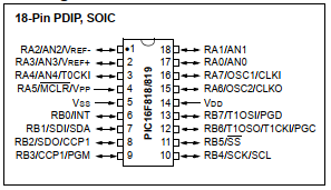
Port B of PIC16F818/819 is an 8-bit wide bi-directional digital I/O port. It’s input/output direction is controlled by its data direction register TRISB. Optionally it has an internal weak pull up resistors individually connects to each pin of Port B. However this 8 resistor network is programmable on/off by software.
 |
| Pin Diagram of PIC16F818 from device’s datasheet |
Port Data and Its Direction Control
Port B locates at 06h and 106h in the Special Function Register (SFR). It’s bi-directional read/write.
Port B Data Direction Register (TRISB) locates at 86h and 186h. Writing ‘1’ to any bit of this register forcing that bit to an input pin, otherwise forcing that bit to an output pin.
Internal Weak Pull Up Resistor
Port B is programmable connect to an internal weak pull up resistors network. There is only one global switch that turn this resistor network on and off. It it’s the PORTB Pull-up Enable bit (nRBPU), of the OPTION register (OPTION_REG) locates at 81h and 181h.
 |
| Option Register of PIC16F818 |
This bit locates at bit 7. Clearing it to enable the internal weak pull up resistor.
Internal Weak Pull Up Resistor Programming in XC8
Using this free version of embedded C compiler, the overall coding is done within a light afford. A simple example shows how to use this feature of PIC microcontroller without adding external resistors to the digital input.
Schematic Diagram
This schematic diagram uses in both physical hardware wiring and software simulation.
 |
| Schematic diagram drawn in Proteus |
RB0 connects to SW2 to turn of the LED D2 whenever it’s pressed. SW1 connects to SW1 to turn off the LED D2 whenever it’s pressed. It’s clock source is an internal oscillator inside the device with a frequency of 31.25kHz.
XC8 Programming
Embedded C program prepare the internal oscillator, I/O direction, and turning on its internal weak pull up resistor.
XC8 Program to use PIC16F818
* internal weak pull up resistor
*/
#include <xc.h>
// PIC16F818 Configuration Bit Settings
// CONFIG
#pragma config FOSC = INTOSCIO // Oscillator Selection bits (INTRC oscillator; port I/O function on both RA6/OSC2/CLKO pin and RA7/OSC1/CLKI pin)
#pragma config WDTE = OFF // Watchdog Timer Enable bit (WDT disabled)
#pragma config PWRTE = OFF // Power-up Timer Enable bit (PWRT disabled)
#pragma config MCLRE = OFF // RA5/MCLR/VPP Pin Function Select bit (RA5/MCLR/VPP pin function is digital I/O, MCLR internally tied to VDD)
#pragma config BOREN = ON // Brown-out Reset Enable bit (BOR enabled)
#pragma config LVP = OFF // Low-Voltage Programming Enable bit (RB3/PGM pin has digital I/O function, HV on MCLR must be used for programming)
#pragma config CPD = OFF // Data EE Memory Code Protection bit (Code protection off)
#pragma config WRT = OFF // Flash Program Memory Write Enable bits (Write protection off)
#pragma config CCPMX = RB2 // CCP1 Pin Selection bit (CCP1 function on RB2)
#pragma config CP = OFF // Flash Program Memory Code Protection bit (Code protection off)
/*Label the inputs outputs*/
#define _ON RB0==0
#define _OFF RB1==0
#define _LED1 RB7
void main(void){
/*Set internal oscillator to 31.25kHz*/
OSCCONbits.IOFS=0x00;
/*Clear Port B*/
PORTB=0x00;
/*RB0.1 Digital Input*/
TRISB=0x03;
/*Turn On Pull Up Resistors*/
OPTION_REGbits.nRBPU=0;
/*Main Program Loop*/
while(1){
if(_ON){
while(_ON);
_LED1=1;
}
if(_OFF){
while(_OFF);
_LED1=0;
}
}
}
This program requires only 2.4% of program memory (Flash).
Simulator and Physical Hardware Testing
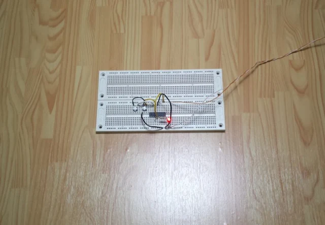
Both simulator and external physical hardware testing produce the same result.
 |
| Program simulation in Proteus |
 |
| Physical hardware test on breadboard |
Click here to download source file.
Accurate measurement made simple with advanced features and precision engineering, ensuring reliability for testing, troubleshooting, and electronic applications. Perfect for professionals and enthusiasts alike.
ReplyDeleteBench Digital Multimeter