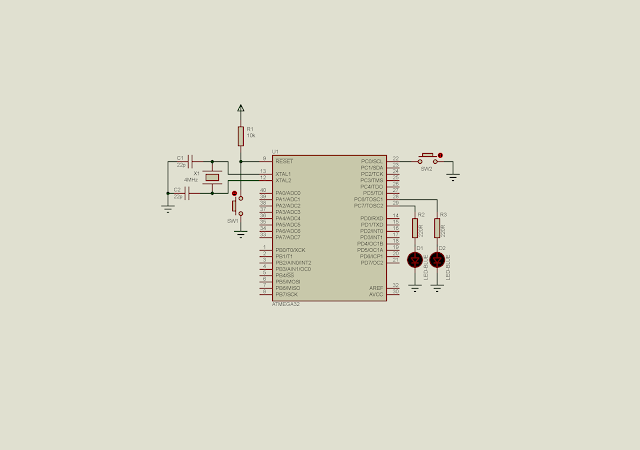
Timer 0 interrupt could be used for creating a square wave output, schedule or setting the period of any running tasks.
In addition to working with some relevant register we have to deal with one more register. The Timer Interrupt Mask (TIMSK) contains some interrupt control bits including the timer 0.
- Timer Interrupt Mask Register (TIMSK)
| BIT 7 | BIT 0 | ||||||
| OCIE2 | TOIE2 | TICIE1 | OCIE1A | OCIE1B | TOIE1 | OCIE0 | TOIE0 |
To program the timer 0 interrupt:
- set up timer and other relevant
- set TOIE0 to '1'
- enable global interrupt by using sei() instruction
- write the ISR
Timer 0 interrupt vector locate at 0x0016. In AVR-GCC timer 0 interrupt vector named as 'TIMER0_OVF_vect'.
Using a 4 MHz clock, the CPU period is:
I want to find a preload value of TCNT0 to make a 1-millisecond timer interrupt tick.

So it is 16 counts before the interrupt. The TCNT0 preload value is 256 - 16 = 240 or -16.
Source Code:
#include <avr/io.h> #include <avr/interrupt.h>
//A variable to count every 1 mS
unsigned int cnt=0;
int main(void)
{
//Set PortC to Output
DDRC=0xC0;
//Clear PortC
PORTC=0x01;
//Set 1:256 prescaler
TCCR0=0x04;
//Clear overflow flag
TIFR=0x01;
//Enable Timer 0 interrupt
TIMSK=0x01;
//set global interrupt
sei();
while (1)
{
if ((PINC&0x01)==0)
{
while((PINC&0x01)==0);
PORTC^=0x40;
}
}
}
ISR(TIMER0_OVF_vect){
//Load -16 to make 1 mS interrupt time
TCNT0=-16;
cnt+=1;
//Toggle LED every 500 mS
if(cnt>=500){
//Toggle PC0
PORTC^=0x80;
cnt=0;
}
//Clear Flag
TIFR=0x01;
}
Click here to download its source file.


No comments:
Post a Comment