In this previous post, we introduced about using ADC module of PIC16F887. Generally, the voltage references VREF+ and VREF- are internally wired to VDD and VSS, respectively. PIC16F887 could be supplied in a range of 2.0 V to 5.5 V. Generally, the supply voltage is +5 V because most external devices work at +5 V.
Step size is an analog voltage per unit of the ADC resolution.

For VREF+ = +5 V (VDD) and the VREF- = 0 V (VSS), we get the step size of

For example if the ADC result equal to 512, the voltage is,

Similarly, we get find the digital result equivalent to the analog input voltage,
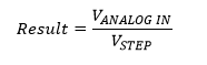
In this example, I use a POT to adjust the analog input voltage varies from 0 to +5 V. To find the voltage we can use the equations listed above. But we can use another short form as,

In the C program, we must use the floating point to measure the analog voltage.
 |
| Schematic diagram. RB0 is AN12 analog input, measuring the input voltage from 0 to +5 V. PORTC and PORTD display the measuring voltage with one floating point. |
The C source code:
#include<xc.h>
// PIC16F887 Configuration Bit Settings
// CONFIG1
#pragma config FOSC = XT
#pragma config WDTE = OFF
#pragma config PWRTE = OFF
#pragma config MCLRE = ON
#pragma config CP = OFF
#pragma config CPD = OFF
#pragma config BOREN = ON
#pragma config IESO = ON
#pragma config FCMEN = ON
#pragma config LVP = ON
// CONFIG2
#pragma config BOR4V = BOR40V
#pragma config WRT = OFF
/*_XTAL_FREQ use for __delay*/
#define _XTAL_FREQ 4000000

void driveDisplays(unsigned int analogRead){
 unsigned char ssd[16]={0x3F,0x06,0x5B,0x4F,0x66,0x6D,0x7D,
 0x07,0x7F,0x6F,0x77,0x7C,0x39,0x5E,0x79,0x71};
 float voltage;
 int _voltage;
 /*Voltage Calculation*/
 voltage=5*((float)analogRead/1024);
 _voltage=voltage*10;

 /*Decimal Place*/
 PORTD=0x00;
 PORTC=ssd[_voltage/10]|0x80;
 PORTD=0x01;
 __delay_ms(10);
 /*Floating point*/
 PORTD=0x00;
 PORTC=ssd[_voltage%10];
 PORTD=0x02;
 __delay_ms(10);
}
unsigned int readADC(void){
    GO=1;
    while(GO);
    __delay_ms(10);
    return (ADRESH<<8)+ADRESL;
}
void main(void){
    unsigned int adcResult;
    /*Analog and digital Port
     Configuration*/
    PORTB=0x00;
    PORTC=0x00;
    PORTD=0x00;
    TRISB=0x01;
    TRISC=0x00;
    TRISD=0x00;
    /*Result is right justify*/
    ADFM=1;
    /*By default is analog,
     but again set it to analog*/
    ANS12=1;
    /*Select FRC Clock of ADC module*/
    ADCON0bits.ADCS=0x03;
    /*Turn on ADC Module*/
    ADON=1;
    /*Select AN12 RB0*/
    ADCON0bits.CHS=0b1100;
    /*initiate a conversion*/
    GO=1;
    /*Wait until GO=0 "done"*/
    while(GO);
    while(1){
        adcResult=readADC();
        driveDisplays(adcResult);
        __delay_ms(20);
    }
}
 |
| Simulation screen shot. The measuring voltage displays 3.9 V DC. |
No comments:
Post a Comment