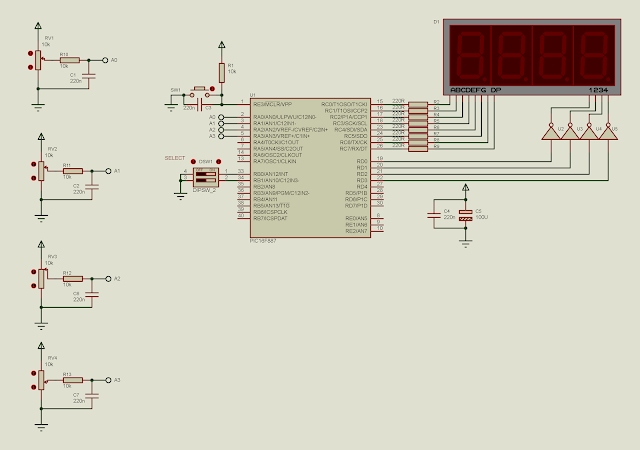
As we can see in the previous post, the analog input channels could be selected by the CHS bits of the ADCON0 register.
In this example I use the ADC module to read four input analog pins RA0, RA1, RA2 and RA3. The selection is made by A 2 positions DIP switch. This DIP switch could make four values. This value make the selection of analog channel.
The overall process is 80 percents similar to the previous one.
Source code is here.
#include<xc.h>
// PIC16F887 Configuration Bit Settings
// CONFIG1
#pragma config FOSC = XT
#pragma config WDTE = OFF
#pragma config PWRTE = OFF
#pragma config MCLRE = ON
#pragma config CP = OFF
#pragma config CPD = OFF
#pragma config BOREN = ON
#pragma config IESO = ON
#pragma config FCMEN = ON
#pragma config LVP = ON
// CONFIG2
#pragma config BOR4V = BOR40V
#pragma config WRT = OFF
/*_XTAL_FREQ use for __delay*/
#define _XTAL_FREQ 4000000

void driveDisplays(unsigned int cnt){
 unsigned char ssd[16]={0x3F,0x06,0x5B,0x4F,0x66,0x6D,0x7D,
 0x07,0x7F,0x6F,0x77,0x7C,0x39,0x5E,0x79,0x71};
 //Digit 4 1000's
 PORTD=0x00;
 PORTC=ssd[cnt/1000];
 PORTD=0x01;
 __delay_ms(10);
 //Digit 3 100's
 PORTD=0x00;
 PORTC=ssd[(cnt%1000)/100];
 PORTD=0x02;
 __delay_ms(10);
 //Digit 2 10's
 PORTD=0x00;
 PORTC=ssd[(cnt%100)/10];
 PORTD=0x04;
 __delay_ms(10);
 //Digit 1 1's
 PORTD=0x00;
 PORTC=ssd[cnt%10];
 PORTD=0x08;
 __delay_ms(10);
}
unsigned int readADC(void){
    ADCON0bits.CHS=PORTB;
    GO=1;
    while(GO);
    __delay_ms(10);
    return (ADRESH<<8)+ADRESL;
}
void main(void){
    unsigned int adcResult;
    /*Analog and digital Port
     Configuration*/
    PORTB=0x00;
    PORTC=0x00;
    PORTD=0x00;
    TRISB=0x03;
    TRISC=0x00;
    TRISD=0x00;
    /*PORTB has no analog inputs*/
    ANSELH=0x00;
    /*Enable Weak Pull ups*/
    nRBPU=0;
    /*Turn on RB0 and RB1
     Weak Pull Up resistor*/
    WPUB=0x03;
    /*Result is right justify*/
    ADFM=1;
    /*Set some analog pins of PORTA*/
    ANSEL=0x0F;
    /*Select FRC Clock of ADC module*/
    ADCON0bits.ADCS=0x03;
    /*Turn on ADC Module*/
    ADON=1;
    /*By default select AN0*/
    ADCON0bits.CHS=0b0000;
    /*initiate a conversion*/
    GO=1;
    /*Wait until GO=0 "done"*/
    while(GO);
    while(1){
        adcResult=readADC();
        driveDisplays(adcResult);
    }
}
 |
| A simulation screen shot. The ADC module is reading the analog voltage input fed from RA3. The result is 2.5 V which is 511 in digital representation. |

No comments:
Post a Comment