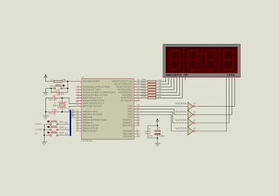
Here's an example of implementing the interrupt on change of PIC16F887. In this example, I use only three interrupt on change pins RB0 RB1 and RB2. When the interrupt occurred, We will process the counting in the ISR.
The main program loop just display the counting result on a four-digit multiplexed seven-segments display.
For more information about multiplexing the display click here.
 |
| Schematic diagram. RB0, RB1 and RB2 implement the IOCB to process the up/down and reset counting. PortC uses to output the numbers. PortD uses to control the 4 digits. |
Source code is written using XC8.
#include<xc.h>
// PIC16F887 Configuration Bit Settings
// CONFIG1
#pragma config FOSC = XT
#pragma config WDTE = OFF
#pragma config PWRTE = OFF
#pragma config MCLRE = ON
#pragma config CP = OFF
#pragma config CPD = OFF
#pragma config BOREN = ON
#pragma config IESO = ON
#pragma config FCMEN = ON
#pragma config LVP = ON
// CONFIG2
#pragma config BOR4V = BOR40V
#pragma config WRT = OFF
#define _XTAL_FREQ 4000000
unsigned int counter=0;
/*Interrupt service routine*/
void interrupt _ISR(void){
    /*looking for portB interrupt
     on change by checking RBIF*/
    if(RBIF){
        /*Test individual pin*/
        if(RB0==0)  {
            if(counter<0)
                counter-=1;
        }
        if(RB1==0)  counter=0;
        if(RB2==0)  {
            if(counter<1000)
                counter+=1;
        }
        RBIF=0;
    }
}
void driveDisplays(unsigned int cnt){
    unsigned char ssd[16]={0x3F,0x06,0x5B,0x4F,0x66,0x6D,0x7D,
 0x07,0x7F,0x6F,0x77,0x7C,0x39,0x5E,0x79,0x71};
 //Digit 4 1000's
 PORTD=0x00;
 PORTC=ssd[cnt/1000];
 PORTD=0x08;
 __delay_ms(10);
 //Digit 3 100's
 PORTD=0x00;
 PORTC=ssd[(cnt%1000)/100];
 PORTD=0x04;
 __delay_ms(10);
 //Digit 2 10's
 PORTD=0x00;
 PORTC=ssd[(cnt%100)/10];
 PORTD=0x02;
 __delay_ms(10);
 //Digit 1 1's
 PORTD=0x00;
 PORTC=ssd[cnt%10];
 PORTD=0x01;
 __delay_ms(10);
}
void main(){
    /*clear PortB*/
    PORTB=0x00;
    /*Clear PortC*/
    PORTC=0x00;
    /*clear PortD*/
    PORTD=0x00;
    /*PortC Output*/
    TRISC=0x00;
    /*PortD as output*/
    TRISD=0x00;
    /*PortB0.3 input*/
    TRISB=0x07;
    /*disable all analog input of portB*/
    ANSELH=0;
    /*turn on global weak pull up*/
    nRBPU=0;
    /*Turn on pull up resistor from RB0 to RB3*/
    WPUB=0x07;
    /*enable portB interrupt on change
     of all pins*/
    IOCB=0x07;
    RBIE=1;
    /*enable global interrupt*/
    GIE=1;    /*program main loop just do
    the multiplexing display*/
    while(1) driveDisplays(counter);
}
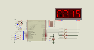
I took a screen shot while simulating.
 |
| A simulation screen shot. The counting reach 15. The program main loop keeps track only for driving the multiplexed display. |
No comments:
Post a Comment