Learn To Write Code For 8051, Arduino, AVR, dsPIC, PIC, STM32 ARM Microcontroller, etc.
Coding Embedded Controller With C/C++.
Printed Circuit Board (PCB) Project For Electronics Hobbyists.
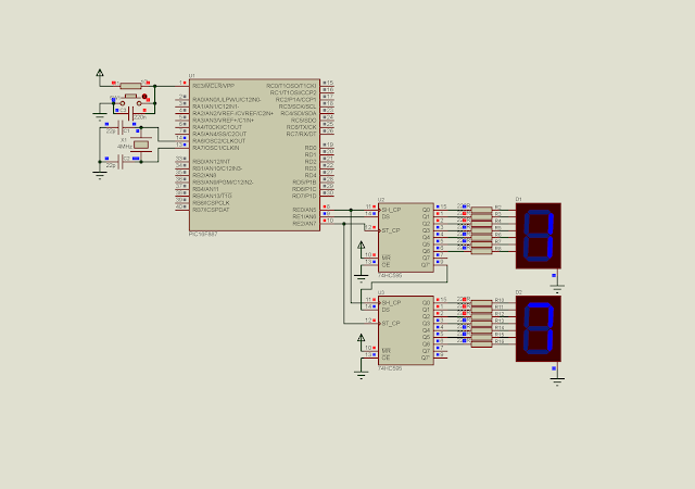
The 74HC595 shift registers is a serial in parallel out shift register type. We just use three digital pins to send the data the register. Using these three wires could drive multiple of this IC.
A Light dependent resistor (LDR) is a resistor whose resistance varies depend on the light source it absorbs. Its electrical resistance decrease up on the intensity of light. With this feature we can create an electric circuit to create a variable output voltage fed to the MCU ADC. It usually used for controlling the output lamp in house.
Some LDR I posses.
A negative temperature coefficient thermistor (NTC) is a resistor whose resistance decrease up on the heat it absorbs. It usually used for controlling the output cooling fan speed.
Some 10k NTC I use for my own workshop
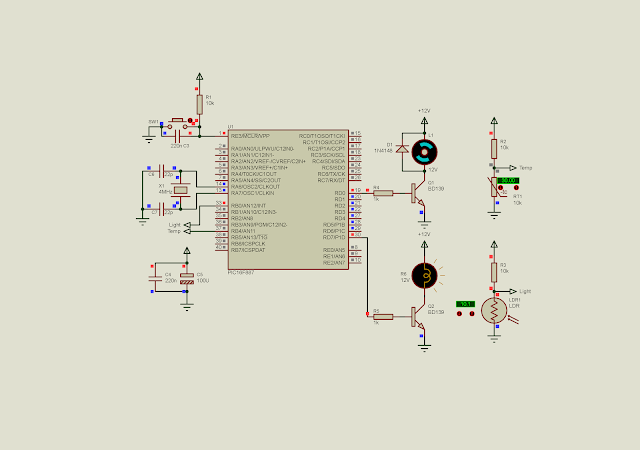
In this example, I use an LDR for turning a lamp on and off. An NTC is used for turning the output fan on and off.
LDR create a variable output analog voltage fed to AN12. Its output is a lamp controlled
by RD7. NTC fed an analog output voltage to AN11 with the corresponding RD0 DC fan
motor output.
The program use timer 0 to schedule the ADC reading every one second. ADC conversion doesn't use any ADC interrupt.
#include<xc.h>
// PIC16F887 Configuration Bit Settings
// CONFIG1
#pragma config FOSC = XT
#pragma config WDTE = OFF
#pragma config PWRTE = OFF
#pragma config MCLRE = ON
#pragma config CP = OFF
#pragma config CPD = OFF
#pragma config BOREN = ON
#pragma config IESO = ON
#pragma config FCMEN = ON
#pragma config LVP = ON
// CONFIG2
#pragma config BOR4V = BOR40V
#pragma config WRT = OFF
/*_XTAL_FREQ use for __delay*/
#define _XTAL_FREQ 4000000
void portSetup(void){
    /*Analog and digital Port
     Configuration*/
    PORTB=0x00;
    PORTD=0x00;
    TRISB0=1;
    TRISB4=1;
    TRISD=0x00;
}
void adcSetup(void){
    /*Result is right justify*/
    ADFM=1;
    /*By default is analog,
     but again set it to analog*/
    ANS12=1;
    ANS11=1;
    /*Select FRC Clock of ADC module*/
    ADCON0bits.ADCS=0x03;
    /*Turn on ADC Module*/
    ADON=1;
    GO=1;
    while(GO);
}
void interruptSetup(void){
    /*Select FOSC*/
    T0CS=0;
    /*Select timer 0 Prescaler*/
    PSA=0;
    /*Enable Timer 0 Overflow
     interrupt*/
    T0IE=1;
    /*Turn on Global interrupt
     Control*/
    GIE=1;
    /*Clear interrupt flag*/
    T0IF=0;
    /*Clear timer 0 register*/
    TMR0=0;
}
unsigned int adcResult;
unsigned char oneSecondTick=0;
void main(void){
    portSetup();
    adcSetup();
    interruptSetup();
    while(1){
        /*If it's one second*/
        if(oneSecondTick>=15){
        /*Select NTC*/
        ADCON0bits.CHS=0x0B;
        __delay_ms(10);
        GO=1;
        while(GO);
        adcResult=(ADRESH<<8)+ADRESL;
        RD0=(adcResult>512)?0:1;
        /*Select LDR*/
        ADCON0bits.CHS=0x0C;
        __delay_ms(10);
        GO=1;
        while(GO);
        adcResult=(ADRESH<<8)+ADRESL;
        RD7=(adcResult<512)?0:1;
        oneSecondTick=0;
        }
    }
}
void interrupt _ISR(void){
    /*If timer 0 Overflow*/
    if(T0IF){
        oneSecondTick+=1;
        T0IF=0;
    }
}
It is just a software simulation. In the physical hardware test we can find an appropriate value of ADC result to fit the application.
The ADC module could trigger an interrupt flag when the reading is completed. Using the interrupt makes the running tasks more effective since it doesn't need to wait for reading completion in the main program loop.
To use the ADC interrupt, we must enable the,
Global interrupt control bit (GIE)of the INTCON register
ADC interrupt enable bit (ADIE) of the PIE1 register,
and clear the ADC complete reading interrupt flag (ADIF) of the PIR1 register.
To read the ADC using interrupt method,
set 'GO' of the ADCON0 to '1'
test the ADIF flag
if ADIF = 1, we can get the ADC result
clear ADIF
In this example, I use ADC interrupt to return a completed ADC reading result. Timer 0 is used for initiating the ADC reading for every one second. Both ADC and timer use interrupt ISR.
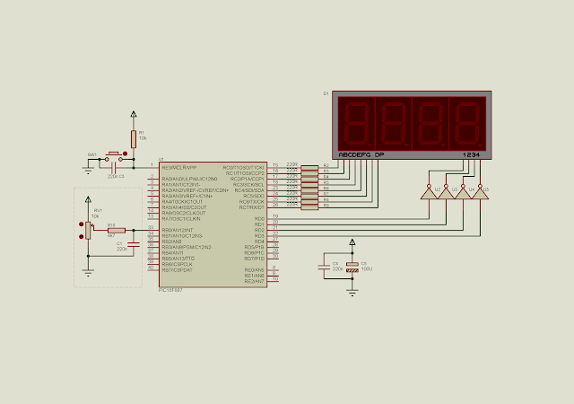
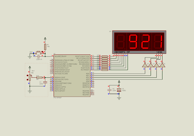
Analog voltage input fed to AN12. A multiplexed SSD display the ADC reading
result in decimal.
C source code's here:
#include<xc.h>
// PIC16F887 Configuration Bit Settings
// CONFIG1
#pragma config FOSC = XT
#pragma config WDTE = OFF
#pragma config PWRTE = OFF
#pragma config MCLRE = ON
#pragma config CP = OFF
#pragma config CPD = OFF
#pragma config BOREN = ON
#pragma config IESO = ON
#pragma config FCMEN = ON
#pragma config LVP = ON
// CONFIG2
#pragma config BOR4V = BOR40V
#pragma config WRT = OFF
/*_XTAL_FREQ use for __delay*/
#define _XTAL_FREQ 4000000

void driveDisplays(unsigned int result){
 unsigned char ssd[16]={0x3F,0x06,0x5B,0x4F,0x66,0x6D,0x7D,
 0x07,0x7F,0x6F,0x77,0x7C,0x39,0x5E,0x79,0x71};
 //Digit 1 1000's
 PORTD=0x00;
 PORTC=ssd[result/1000];
 if(result>=1000)PORTD=0x01;
 __delay_ms(10);
 //Digit 2 100's
 PORTD=0x00;
 PORTC=ssd[(result%1000)/100];
 if(result>=100)
     PORTD=0x02;
 __delay_ms(10);
 //Digit 3 10's
 PORTD=0x00;
 PORTC=ssd[(result%100)/10];
 if(result>=10)
     PORTD=0x04;
 __delay_ms(10);
 //Digit 4 1's
 PORTD=0x00;
 PORTC=ssd[result%10];
 PORTD=0x08;
 __delay_ms(10);
}
unsigned int readADC(void){
    GO=1;
    while(GO);
    __delay_ms(10);
    return (ADRESH<<8)+ADRESL;
}
void portSetup(void){
    /*Analog and digital Port
     Configuration*/
    PORTB=0x00;
    PORTC=0x00;
    PORTD=0x00;
    TRISB=0x01;
    TRISC=0x00;
    TRISD=0x00;
}
void adcSetup(void){
    /*Result is right justify*/
    ADFM=1;
    /*By default is analog,
     but again set it to analog*/
    ANS12=1;
    /*Select FRC Clock of ADC module*/
    ADCON0bits.ADCS=0x03;
    /*Turn on ADC Module*/
    ADON=1;
    /*Select AN12 RB0*/
    ADCON0bits.CHS=0b1100;

}
void interruptSetup(void){
    /*Select FOSC*/
    T0CS=0;
    /*Select timer 0 Prescaler*/
    PSA=0;
    /*Enable Timer 0 Overflow
     interrupt*/
    T0IE=1;
    /*Turn on Global interrupt
     Control*/
    GIE=1;
    /*Enable Peripheral Interrupt*/
    PEIE=1;
    /*Enable ADC complete reading
     interrupt*/
    ADIE=1;
    /*Clear ADC interrupt Flag*/
    ADIF=0;
    /*Clear interrupt flag*/
    T0IF=0;
    /*Clear timer 0 register*/
    TMR0=0;
}
unsigned int adcResult;
unsigned char oneSecondTick=0;
void main(void){
    portSetup();
    adcSetup();
    interruptSetup();
    while(1){
        driveDisplays(adcResult);
    }
}
void interrupt _ISR(void){
    /*If timer 0 Overflow*/
    if(T0IF){
        oneSecondTick+=1;
        T0IF=0;
    }
    /*If it's one second*/
    if(oneSecondTick>=15){
        oneSecondTick=0;
        GO=1;
    }
    /*If ADC reading completed*/
      if(ADIF){
        adcResult=(ADRESH<<8)+ADRESL;
        ADIF=0;
    }
}
The ADC reading acquires 921 digital value result in decimal.