A Light dependent resistor (LDR) is a resistor whose resistance varies depend on the light source it absorbs. Its electrical resistance decrease up on the intensity of light. With this feature we can create an electric circuit to create a variable output voltage fed to the MCU ADC. It usually used for controlling the output lamp in house.
 |
| Some LDR I posses. |
A negative temperature coefficient thermistor (NTC) is a resistor whose resistance decrease up on the heat it absorbs. It usually used for controlling the output cooling fan speed.
 |
| Some 10k NTC I use for my own workshop |
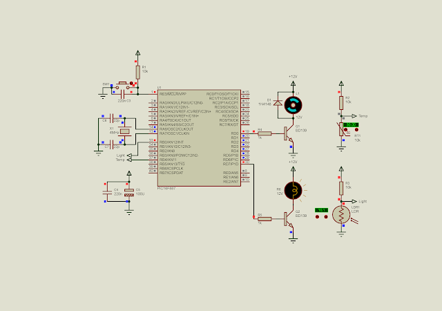
In this example, I use an LDR for turning a lamp on and off. An NTC is used for turning the output fan on and off.
 |
| LDR create a variable output analog voltage fed to AN12. Its output is a lamp controlled by RD7. NTC fed an analog output voltage to AN11 with the corresponding RD0 DC fan motor output. |
The program use timer 0 to schedule the ADC reading every one second. ADC conversion doesn't use any ADC interrupt.
#include<xc.h>
// PIC16F887 Configuration Bit Settings
// CONFIG1
#pragma config FOSC = XT
#pragma config WDTE = OFF
#pragma config PWRTE = OFF
#pragma config MCLRE = ON
#pragma config CP = OFF
#pragma config CPD = OFF
#pragma config BOREN = ON
#pragma config IESO = ON
#pragma config FCMEN = ON
#pragma config LVP = ON
// CONFIG2
#pragma config BOR4V = BOR40V
#pragma config WRT = OFF
/*_XTAL_FREQ use for __delay*/
#define _XTAL_FREQ 4000000
void portSetup(void){
    /*Analog and digital Port
     Configuration*/
    PORTB=0x00;
    PORTD=0x00;
    TRISB0=1;
    TRISB4=1;
    TRISD=0x00;
}
void adcSetup(void){
    /*Result is right justify*/
    ADFM=1;
    /*By default is analog,
     but again set it to analog*/
    ANS12=1;
    ANS11=1;
    /*Select FRC Clock of ADC module*/
    ADCON0bits.ADCS=0x03;
    /*Turn on ADC Module*/
    ADON=1;
    GO=1;
    while(GO);
}
void interruptSetup(void){
    /*Select FOSC*/
    T0CS=0;
    /*Select timer 0 Prescaler*/
    PSA=0;
    /*Enable Timer 0 Overflow
     interrupt*/
    T0IE=1;
    /*Turn on Global interrupt
     Control*/
    GIE=1;
    /*Clear interrupt flag*/
    T0IF=0;
    /*Clear timer 0 register*/
    TMR0=0;
}
unsigned int adcResult;
unsigned char oneSecondTick=0;
void main(void){
    portSetup();
    adcSetup();
    interruptSetup();
    while(1){
        /*If it's one second*/
        if(oneSecondTick>=15){
        /*Select NTC*/
        ADCON0bits.CHS=0x0B;
        __delay_ms(10);
        GO=1;
        while(GO);
        adcResult=(ADRESH<<8)+ADRESL;
        RD0=(adcResult>512)?0:1;
        /*Select LDR*/
        ADCON0bits.CHS=0x0C;
        __delay_ms(10);
        GO=1;
        while(GO);
        adcResult=(ADRESH<<8)+ADRESL;
        RD7=(adcResult<512)?0:1;
        oneSecondTick=0;
        }
    }
}
void interrupt _ISR(void){
    /*If timer 0 Overflow*/
    if(T0IF){
        oneSecondTick+=1;
        T0IF=0;
    }
}
It is just a software simulation. In the physical hardware test we can find an appropriate value of ADC result to fit the application.
 |
| A sample of the running program in software |
Thank you for sharing such a well-written and insightful post! I appreciate how clearly you presented the information, making it both informative and engaging. Your unique perspective really adds value to the topic. Looking forward to reading more of your great content in the future!
ReplyDeleteThermistors
Enrgtech
Outstanding post—clear, concise, and informative. I truly enjoyed reading it and learned a lot. Looking forward to more valuable content like this. Keep it up!
ReplyDeleteThermistors
Enrgtech
discountfinderpro