Overview
A character LCD is a good replacement for a conventional dot matrix display. It has a build-in LCD controller especially the HITACHI HD44780 chip. Characters are send once consuming a little microprocessor executing time.
The HD44780 is very popular among electronics hobbyists and small electronics digital control project. It use an 8-bit or even 4-bit data bus with a few control pins. It has various optional outputs, 8x2, 16x1, 16x2, 20x2, 16x4, etc. It can show ASCII, Japanese, and even any custom characters.
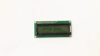
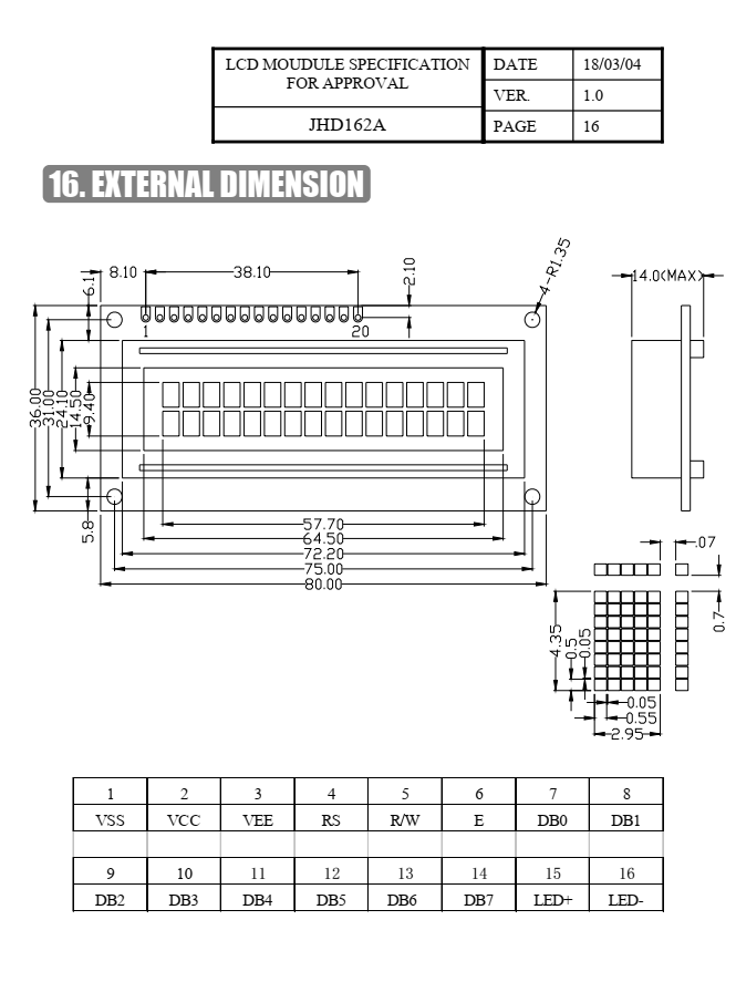
Most of Chinese LCD parts use Chip-On-Board assembling with ceramic coating. So we can not see its controller chip. The picture above is an JHD1602A LCD module.
Using an 8-bit data transfer mode is very simple. We just need send command and data to this display module.
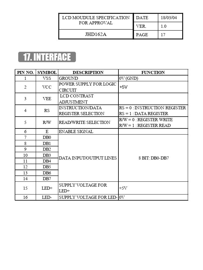
Register Select (RS) allow us to choose between command (RS=0) and data (RS=1). Read or Write (R/W) must be wired to GND because we just need to send command or data to the LCD controller. Enable (E) is active high allowing the command or data latched into the LCD controller via its 8-bit data bus (DB) port.
Interfacing and Programming Using MPLABX IDE
I use the current version of MPLABX IDE of v6.15 and XC8 compiler v2.36. This C compiler is much easier to use than PIC Assembly language. I just use free version without code optimization.
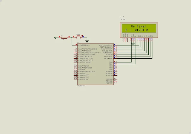
In this example, the LCD show operating time since it started up.
I use its 8MHz internal RC oscillator. Click here to download its source file.
.jpg)
No comments:
Post a Comment