Device Overview
The DS18B20 is a digital thermometer that able to convert the temperature from -55 to +125 degree Celsius. The controller communicates with this temperature sensor using a 1-Wire bus. So this device requires only three wires including GND, VCC, and data line. Furthermore it can use data line to power the device eliminating the VCC.
 |
| DS18B20 Pin Configuration |
 |
| DS18B20 In TO-92 Package |
A TO-92 package is a typical package for hardware experiment.
 |
| A Typical Connection Between Microprocessor And DS18B20 |
 |
| Using Multiple Devices Over A 1-Wire Bus |
It has its own 64-bit ROM unique ID allowing the controller interface to multiple DS18B20 devices over a 1-Wire bus.
 |
| DS18B20 64-Bit ROM Area |
If there is only one DS18B20 over a 1-Wire bus, it just need to skip ROM search. The controller just need issue a skip ROM, convert, and read scratch pad command.
 |
| DS18B20 Memory Map |
 |
| DS18B20 Temperature Data Format |
Scratchpad contains 9 bytes of data. Converted temperature consists of two bytes, BYTE 0 and BYTE 1 of device's scratch-pad. It contains sign, decimal temperature data, and fraction in degree Celsius.
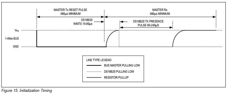
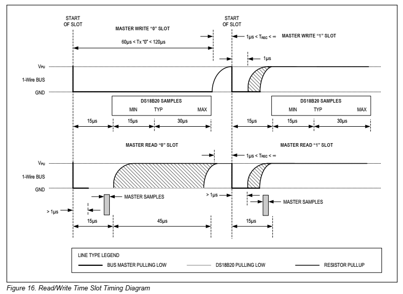
To interface with this 1-Wire device, the micro-controller have to prepare a correct timing for its I/O as follow.
 |
| DS18B20 Initialization Timing |
 |
| DS18B20 Read/Write Time Slot |
This device has two command categories, ROM Commands and Function Commands. ROM commands are not use as the micro-controller just need to get the temperature from a single thermometer on 1-wire bus. DS18B20 ROM Commands
- Search ROM [F0h]
- Read ROM [33h]
- Match ROM [55h]
- Skip ROM [CCh]
- Alarm Search [ECh]
DS18B20 Function Commands
- Convert Temperature [44h]
- Write Scratchpad [4Eh]
- Read Scracthpad [BEh]
- Copy Scratchpad [48h]
- Recall EEPROM [B8h]
- Read Power Supply [B4h]
For full explanation for these command please read the device's data sheet.
XC8 Programming
I use the MPLABX IDE 1.51 with XC8 v2.36 C compiler for PIC micro-controller. I need to write about five C functions to interact with this device. These C functions I followed an application note published by ANALOG DEVICES, "Interfacing the DS18X20/DS1822 1-Wire® Temperature Sensor in a Microcontroller Environment". This example use the 8051 micro-controller.
 |
| Simulating Program In Proteus |
 |
| Multiplexing Seven-Segment Display |
 |
| PIC16F84A In P-DIP Package From Microchip Website |
In this example I use a simple 8-bit micro-controller PIC16F84A to get the temperature from this device. The output device is a simple 4-digit common cathode multiplexing display. For the first conversion time, the thermometer yield 85 degree Celsius but I skip this data.
#include<xc.h>
// PIC16F84A Configuration Bit Settings
// CONFIG
#pragma config FOSC = XT // Oscillator Selection bits (XT oscillator)
#pragma config WDTE = OFF // Watchdog Timer (WDT disabled)
#pragma config PWRTE = OFF // Power-up Timer Enable bit (Power-up Timer is disabled)
#pragma config CP = OFF // Code Protection bit (Code protection disabled)
#define _XTAL_FREQ 4000000
#define DQ RA4
#define DQ_DIR TRISA4
unsigned char ow_reset(void){
unsigned char presence;
DQ_DIR=0;
DQ=0;
__delay_us(480);
DQ=1;
__delay_us(70);
DQ_DIR=1;
presence=DQ;
__delay_us(425);
return presence;
}
unsigned char readBit(void){
DQ_DIR=0;
DQ=0;
DQ_DIR=1;
__delay_us(15);
return DQ;
}
void writeBit(char bitVal){
DQ_DIR=0;
DQ=0;
if(bitVal==1) DQ=1;
__delay_us(104);
DQ=1;
}
unsigned char readByte(void){
unsigned char i;
unsigned char value=0;
for(i=0;i<8;i++){
if(readBit()) value|=0x01<<i;
__delay_us(96);
}
return value;
}
void writeByte(char val){
unsigned char i;
unsigned char temp;
for(i=0;i<8;i++){
temp=val>>i;
temp&=0x01;
writeBit(temp);
}
__delay_us(104);
}
void main(void){
unsigned char LSB,MSB;
unsigned char get[9];
unsigned int temp;
//unsigned char ssd[16]={0x3F,0x06,0x5B,0x4F,0x66,0x6D,0x7D,0x07,0x7F,0x6F,0x77,0x7C,0x39,0x5E,0x79,0x71};
unsigned char ssd[10]={0x3F,0x06,0x5B,0x4F,0x66,0x6D,0x7D,0x07,0x7F,0x6F};
PORTB=0x00;
TRISB=0x00;
PORTA=0x00;
TRISA=0x00;
ow_reset();
writeByte(0xCC);
writeByte(0x44);
__delay_us(104);
ow_reset();
writeByte(0xCC);
writeByte(0xBE);
for(int i=0;i<9;i++) get[i]=readByte();
__delay_ms(800);
while(1){
ow_reset();
writeByte(0xCC);
writeByte(0x44);
__delay_us(104);
ow_reset();
writeByte(0xCC);
writeByte(0xBE);
for(int i=0;i<9;i++) get[i]=readByte();
MSB=get[1];
LSB=get[0];
temp=(MSB<<8)+LSB;
temp>>=4;
LSB=0x0F&LSB;
if(LSB^0x08) LSB=0;
else LSB=5;
//temp&=0x00FF;
//PORTB=temp;
__delay_ms(10);
PORTA=0x00;
PORTB=ssd[temp/100];
if(temp/100) RA0=1;
__delay_ms(5);
PORTA=0x00;
PORTB=ssd[(temp%100)/10];
RA1=1;
__delay_ms(5);
PORTA=0x00;
PORTB=ssd[temp%10]|0x80;
RA2=1;
__delay_ms(5);
PORTA=0x00;
PORTB=ssd[LSB];
RA3=1;
__delay_ms(5);
}
}
This program uses half of device program space and about 80% of device data space. Click here to download its source file.
 |
| RAM ROM Usage In PIC16F84A |
CCS PICC provide a touch sensor library similar to the DS18B20. MikroC also has a 1-Wire library for its supported devices. Arduino has a lot of libraries for various type of sensors including this device.


No comments:
Post a Comment