Introduction
ESP8266 is a system on a chip (SoC) specializing for Internet of Things (IoT) programming. It's very popular, and ease of programming. Most this chip is programmed using Arduino IDE with a lot of programming examples.
 |
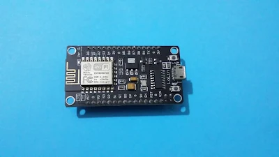
| Nodemcu V3 module #1 |
 |
| Nodemcu V3 module #2 |
Nodemcu is single board computer containing esp8266 chip. It's ready to use with a factory programmed firmware. As shown in picture above, it has I/O connections, UART bridge for serial communication/program uploading, and on-board LED.
My Design
I'm interested in I2C devices communication with this module. I copped with I/O expanding while I was programming for my IoT project. I select MCP23017 for port expanding cause of it uses I2C requiring only two wires on a single bus.
 |
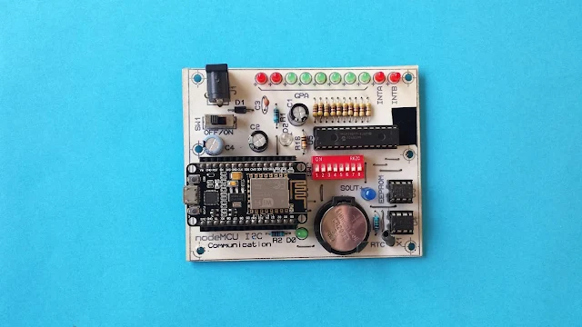
| My ready-to-use prototype |
I added DS1307 real time clock IC, and an EEPROM chip. These three on board devices use I2C connected on a single two-wire bus. Hence other remaining I/O of esp8266 can be use for other hardware's interfacing - sensor, LCD, etc.
 |
| Copper soldering side |
I made this board by hands using dry film method at copper side. At components side I use toner transfer method, sticking laser printer toner text with PCB panel.
I design this PCB using Proteus as I am experienced with this software a decade now.
Schematic:
 |
| Schematic diagram designed using Proteus |
 |
| PCB design preview |
 |
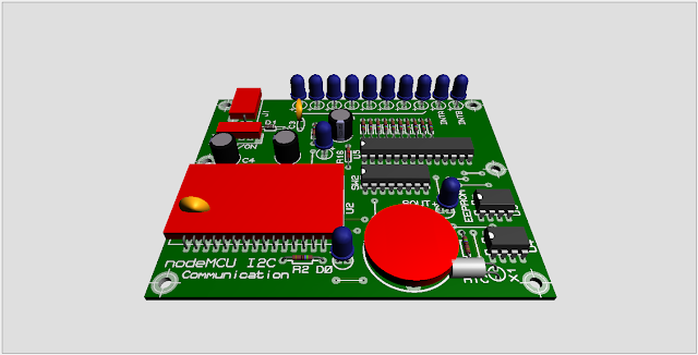
| Preview of 3D design in Proteus |
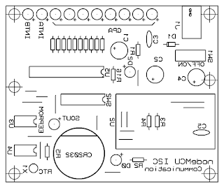
I put its copper layer side and legend side below.
 |
| Copper layer - Normal |
 |
| Component side - Miror |
Click here to download this PCB design package.
No comments:
Post a Comment