- a delay timer
- a frequency generator
- a software controlled PWM
To make it run in timer mode, we must do a software configuration as follow:
- clear T0CS
- select a preferring prescaler, with the PSA and PS bits.
- clear timer 0 interrupt flag (T0IF)
- clear timer 0
An example program below I use timer to create a delay to blink an LED every one second. I assign the T0CS to work as timer mode. I clear the PSA bit to select the timer 0 prescaler rate. The PSA default values is 0x07, giving a 1:256 prescaler value.
The MCU clock is 4 MHz. With the pipe-lining technique of PIC architecture, the instruction clock is a quarter of the MCU clock. So,

The period the instruction clock is,

Timer 0 prescaler is 1:256, giving 256 x 1 micro second = 256 micro seconds. So TMR0 is increase at every 256 micro seconds. TMR0 overflows when it rolls from 0xFF to 0x00, setting a the interrupt flag T0IF. The period that interrupt occurs is 256 x 256 micro seconds = 65 milli seconds.
Using this 65 milli seconds period, I want to toggle an LED every 1 second. So,
every 15 timer 0 overflow make one second.
 |
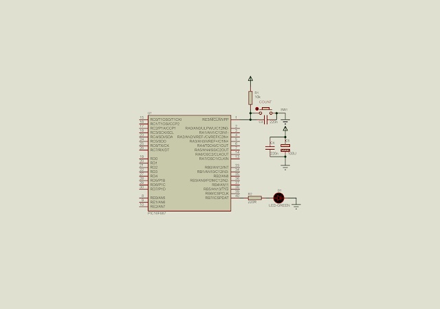
| Schematic diagram. PIC16F887 clocks at 4 MHz. The instruction clock is 1 MHz. RB7 toggles every 1 second. |
The C source code is here.
#include "xc.h"
// PIC16F887 Configuration Bit Settings
// CONFIG1
#pragma config FOSC = XT
#pragma config WDTE = OFF
#pragma config PWRTE = OFF
#pragma config MCLRE = ON
#pragma config CP = OFF
#pragma config CPD = OFF
#pragma config BOREN = ON
#pragma config IESO = ON
#pragma config FCMEN = ON
#pragma config LVP = OFF
// CONFIG2
#pragma config BOR4V = BOR40V
#pragma config WRT = OFF


void main(){
    unsigned char cnt=0;
    PORTB=0x00;
    TRISB7=0;
    T0CS=0;
    PSA=0;
    T0IF=0;
    TMR0=0;
    while(1){
        if(T0IF){
            cnt+=1;
            T0IF=0;
        }
        if(cnt>=15){
            cnt=0;
            RB7^=1;
        }
    }
}

No comments:
Post a Comment