We can disable the $MCLR reset circuitry by clearing the MCRLE in the CONFIG1 configuration register. When it's cleared, the $MCLR pin is internally connected to VDD.
The 16-bit configuration word register 1 listed below:
| BIT 15 | BIT 8 | ||||||
| N/A | N/A | $DEBUG | LVP | FCMEN | IESO | BOREN1 | BOREN0 |
| BIT 7 | BIT 0 | ||||||
| $CPD | $CP | MCLRE | $PWRTE | WDTE | FOSC2 | FOSC1 | FOSC0 |
In the XC8, we just use the "#pragma" directive to set the configuration like this:
#pragma config MCLRE = OFF
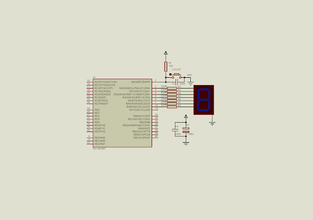
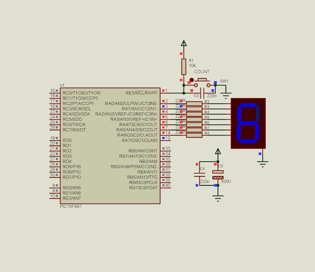
In this example, I use the RE3 pin as a digital input to count the external pulse. PortA used as a digital output port displaying the counting result on a single SSD. The OSC1 and OSC2 pin of PortA used as a digital output as a result of clocking the CPU from the internal RC oscillator with no clock out option.
 |
| Schematic diagram. MCLR pin is internally pulled high. RE3 is a digital input pin counting the button pressed. PORTA output the counting result to a single SSD. |
The XC8 source code:
#include<xc.h>
// PIC16F887 Configuration Bit Settings
// CONFIG1
#pragma config FOSC = INTRC_NOCLKOUT
#pragma config WDTE = OFF
#pragma config PWRTE = OFF
#pragma config MCLRE = OFF
#pragma config CP = OFF
#pragma config CPD = OFF
#pragma config BOREN = ON
#pragma config IESO = ON
#pragma config FCMEN = ON
#pragma config LVP = ON
// CONFIG2
#pragma config BOR4V = BOR40V
#pragma config WRT = OFF
#define _XTAL_FREQ 4000000
#define btnCount RE3
void main(void){
    unsigned char ssd[16]={0x3F,0x06,0x5B,0x4F,0x66,0x6D,0x7D,
        0x07,0x7F,0x6F,0x77,0x7C,0x39,0x5E,0x79,0x71};
    char countButton=0;
    /*Select 4 MHz internal Oscillator*/
    SCS=1;
    OSCCONbits.IRCF=0x06;
    /*clear PortA*/
    PORTA=0x00;
    /*set PortA to output*/
    TRISA=0x00;
    /*clear analog inputs*/
    ANSEL=0x00;
    while(1){
        if(btnCount==0){
            __delay_ms(250);
            countButton+=1;
        }
        if(countButton>15)
            countButton=0;
        PORTA=ssd[countButton];
    }
}
A screen shot the program simulation:
 |
| A simulation screen shot. The counting result fed from RE3 reaches 6. |
No comments:
Post a Comment