By setting the WGM00 of TCCR0 to '1', it will work as the phase correct PWM mode. The polarity of waveform is determined by COM01:00 bits of the TCCR0 register. By giving COM01:00 to 2, the polarity is non inverting. While giving COM01:00 to 3, the polarity is inverting output.
The PWM frequency in this mode is given by:
Back to main tutorial page ATMega32 tutorials in C with Atmel Studio 7.
Again, N is the timer 0 prescaler. As we can see, the timer 0 counter value is 510 doubling the original maximum value of TCNT0. This give a higher resolution of PWM signal.
For example, I use a 4 MHz crystal clock with a prescaler to timer 1:1. The frequency is:
The period T about 128 micro seconds.
Now let do a C coding:
#include <avr/io.h>
int main(void)
{
 //set the duty cycle to about 75%
 OCR0=191;
 //set PB3 to output
 DDRB|=(1<<3);
 /*
 Set phase correct PWM mode with non
 inverting output
 */
 TCCR0|=(1<<COM01)|(1<<WGM00);
 //select 1:1 prescaler
 TCCR0|=(1<<CS00);
    while (1)
    {
    }
}
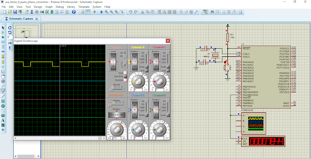
Now let verify the result in the simulation, because I don't have a real oscilloscope.
 |
| Simulation screen shot. The PWM output is 7.81 kHz with a 75% duty cycle |
Back to main tutorial page ATMega32 tutorials in C with Atmel Studio 7.


No comments:
Post a Comment