- fast PWM
- and phase correct PWM
In this example, we use only the fast PWM.
With timer/counter 0 module, an 8-bit comparator is non-stop digital comparator, comparing the value of TCNT0 with the output compare register 0 (OCR0). OCR0 is an 8-bit read/write register with an initial value of 0x00. It must have a preset value.
- Output compare register 0 (OCR0)
| BIT 7 | BIT 0 | ||||||
| D7 | D6 | D5 | D4 | D3 | D2 | D1 | D0 |
 |
| A simplified PWM signal generator module |
When TCNT0 equal to the preset OCR0 (matched), the output compare flag (OCF0) will be set.
At the matched condition, the waveform generator will produce a waveform output to pin PB3. The wave form mode must be select in the TCCR0 register.
To program the PWM we must take notes as follow:
- The value of OCR0 effect the duty cycle of the PWM. A large loaded value of it increase the duty cycle (non inverting mode).
- A large value of timer 0 prescaler decrease the frequency of the PWM.
PWM operating mode could be configured using TCCR0.
- Timer/Counter Control Register 0 (TCCR0)
| BIT 7 | BIT 0 | ||||||
| FOC0 | WGM00 | COM01 | COM00 | WGM01 | CS02 | CS01 | CS00 |
The waveform generation mode bit WGM0:1 set the two mode of PWM.
| WGM1 | WGM0 | Description |
| 1 | 0 | Phase correct PWM |
| 1 | 1 | Fast PWM |
Fast PWM polarity could be configured with compare output mode bit COM0:1.
| COM1 | COM0 | Description |
| 1 | 0 | Clear OC0 pin when the compare is matched (non inverting) |
| 1 | 1 | Set OC0 pin when the compare is matched (inverting) |
As mention in the previous post, the prescaler of timer 0 could be set using CS02:00. To select a 1:1 prescaler, we assign CS00 to '1' and others to '0'.
The frequency of PWM signal generated by timer 0 is:

For example I use 4 MHz crystal with timer 0 prescaler 1:1. The PWM frequency could be:
The PWM period time is:
Now let see this example, I use the calculation listed above and I set the value of OCR0 to 127 to make a 50% duty cycle PWM signal with the frequency of 15.625 kHz.
#include <avr/io.h>

int main(void)
{
 //set the duty cycle to 50%
 OCR0=127;
 //set PB3 to output
 DDRB|=(1<<3);
 /*
 Set fast PWM mode with non
 inverting output
 */
 TCCR0|=(1<<COM01)|(1<<WGM00)|(1<<WGM01);
 //select 1:1 prescaler
 TCCR0|=(1<<CS00);
    while (1)
    {
    }
}
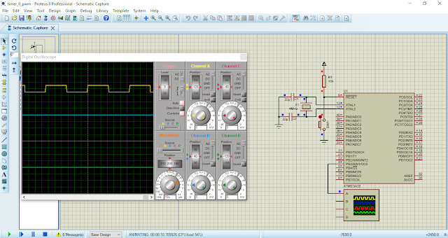
The simulation screen shot shows the PWM signal. Click here to download its source file.
 |
| Simulation screen shot. ATMega32 oscillates from a 4 MHz clock. PB3/OC0 outputs a PWM signal with the frequency of 15.625 kHz and 50% duty cycle. |
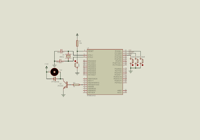
Since OCR0 is readable and writable, we can modify it to change duty cycle of generated PWM. In the following example, I use three switches to increase, reset and decrease the duty cycle. But I change the prescaler of timer 0 to 1:8, reducing the frequency.
 |
| Schematic diagram of new example. Three switches are connected to PC0.2 to adjust duty cycle. PB3/OC0 output the PWM signal. |
C source code is here.
#include <avr/io.h>
#define F_CPU 4000000UL
#include <util/delay.h>
void adjustDutyCycles(void){
 static unsigned char temp=0;
 //increase duty cycle
 if ((PINC&0x01)==0)
 {
  _delay_ms(250);
  if(temp<90) temp+=10;
 }
 //set duty cycle to zero
 if ((PINC&0x02)==0)
 {
  _delay_ms(250);
  temp=0;
 }
 //decrease duty cycle
 if ((PINC&0x04)==0)
 {
  _delay_ms(250);
  if(temp>0) temp-=10;
 }
 OCR0=(0xFF*temp)/100;
}
int main(void)
{
 //PC0.2 inputs
 DDRC=0b11111000;
 //Turn PC0.2 High
 PORTC=0b0000111;
    //set the duty cycle to 50%
 OCR0=0;
 //set PB3 to output
 DDRB|=(1<<3);
 /*
 Set fast PWM mode with non
 inverting output
 */
 TCCR0|=(1<<COM01)|(1<<WGM00)|(1<<WGM01);
 //select 1:8 prescaler
 TCCR0|=(1<<CS01);
    while (1)
    {
  adjustDutyCycles();
    }
}
Click here to download its source file.
Back to main tutorial page ATMega32 tutorials in C with Atmel Studio 7.


No comments:
Post a Comment