PIC16F887 has up to 35 digital inputs outputs, divides into ports. They are:
- PORTA
- PORTB
- PORTC
- PORTD
- and PORTE
 |
| PIC16F887 Pin Diagram |
Each port has its own address locates in the special function register (SFR). They are 8-bit wide and Read/Write.
Port Address
---------------------------
PORTA 0x05
PORTB 0x06
PORTC 0x07
PORTD 0x08
PORTE 0x09
Each Port controlled by a direction register called TRIS. For example, TRISA controls the direction of PortA. They have the corresponding address in the SFR:
TRIS Address
---------------------------
TRISA 0x85
TRISB 0x86
TRISC 0x87
TRISD 0x88
TRISE 0x89
Writing a '1' to TRISx make the corresponding PORTx as a digital input. While writing a '0' to TRISx make the corresponding PORTx as a digital output.
For example, TRISA=0x01 will make RA0 of PORTA as a digital input.
Example:
TRISA=0x0F make RA0...3 as a digital input
TRISB=0xF0 make RB0...3 as a digital output
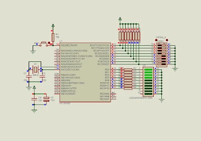
In this example, I use PORTC as a digital input port, reading digital data from a DIP switch.
PORTD is assigned to a digital output port, displaying digital value to LED bar graph.
In XC8, we include xc.h file. It contain all SFR information for selected PIC device.
Source Code:
#include<xc.h>
// CONFIG1
#pragma config FOSC = XT
#pragma config WDTE = ON
#pragma config PWRTE = OFF
#pragma config MCLRE = ON
#pragma config CP = OFF
#pragma config CPD = OFF
#pragma config BOREN = ON
#pragma config IESO = ON
#pragma config FCMEN = ON
#pragma config LVP = ON
// CONFIG2
#pragma config BOR4V = BOR40V
#pragma config WRT = OFF
void main(){
    //Clear PortC
    PORTC=0x00;
    //Clear PortD
    PORTD=0x00;
    //PortC as input
    TRISC=0xFF;
    //PortD as output
    TRISD=0x00;
    while(1){
        PORTD=PORTC;
    }
}
The picture below is a screen shot of simulation.
 |
| A screen shot of the simulation. PORTC read 0x0F from the DIP switch. PORTD write 0x0F to the bar graph LED. |

No comments:
Post a Comment