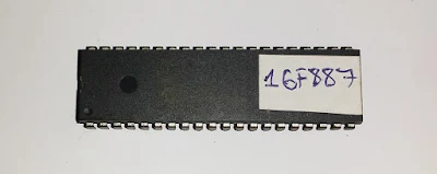
PIC16F887 was released during 2009. It is a mid range 8-bit PIC architecture, designed to replace the popular older one PIC16F887A. However, PIC16F877A still useful in some educations, due to its rich of learning resources.
 |
| PIC16F887 40-pin DIP package |
I saw some major surpluses of PIC16F887 over PIC16F877A:
- Internal RC oscillator up to 8 MHz
- MCLR pin could be disable, and could be used as a digital input
- The 10-bit ADC module has up to 14 channels.
- Digital I/O has up to 35 etc.
For programming migration, there are some special function register differences. We can check them in the device's datasheet.
There are a lot of programming tools for PIC. The programming language could be Assembly, C, Basic, and Pascal etc. C is very popular that I mention here. Some widely used C compilers in the market are:
- MikroC
- CCS PICC
- Hi-Tech PICC
- Microchip XC8
All of them are paid. Hitech PICC was acquired by Microchip Technology, as a result of XC8 C compiler.
XC8 compiler provide three modes:
- free version
- standard version
- pro version
As a hobbyist or a student, we can use XC8 free version with no limit. But the free version doesn't have code optimization and technical support from the manufacturer. In the free version, the generated binary file could be larger.
MPLABX is the IDE for developing the project. In this tutorial I use MPLABX v1.51, and XC8 v1.31.
You can download them for free from Microchip website.
After the installation of MPLABX and XC8 C compiler, open the IDE.
 |
| MPLABX when opened |
Now start a new project. Click File->New Project
Click Next >, In the device type PIC16F887
Click Next > , In the Select Tool, select click Pickit2
Click Next >, select XC8(v1.31)
Click Next > , Type the project name and click Finish.
Now right click on Source Files of the project folder, and click on Empty File
In the File Name, type main.c and click Finish
Click on Window->PIC Memory View -> Configuration Bits
Select the options we need, and click Generate Source Code To Output
In the source code outputs below is the configure bits of the MCU, you can copy them into c source file, or type by hands.
Now, in the main.c file write your file embedded C program:
#include<xc.h>
// CONFIG1
#pragma config FOSC = XT
#pragma config WDTE = ON
#pragma config PWRTE = OFF
#pragma config MCLRE = ON
#pragma config CP = OFF
#pragma config CPD = OFF
#pragma config BOREN = ON
#pragma config IESO = ON
#pragma config FCMEN = ON
#pragma config LVP = ON
// CONFIG2
#pragma config BOR4V = BOR40V
#pragma config WRT = OFF
#define _XTAL_FREQ 40000000
void main(){
    //Clear PortD
    PORTD=0x00;
    //Set PortD to digital output
    TRISD=0x00;
    //main program loop
    while(1){
        PORTD=0x00;
        __delay_ms(500);
        PORTD=0xFF;
        __delay_ms(500);
    }
}
After the completion of coding, press on Build Main Project button.
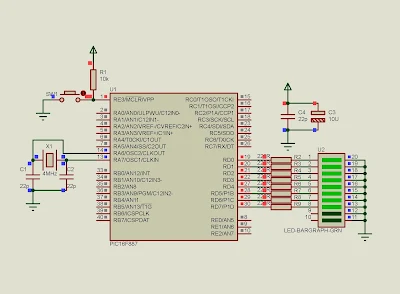
I use Proteus VSM 8 to simulate the program.
 |
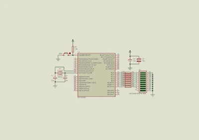
| Simulation Schematic, PIC16F887 run at +5 V DC, clocks at 4 MHz. PORTD connects to LED bar graph. |
 |
| A screen shot of PIC16F887 Proteus simulation |


No comments:
Post a Comment