To use this internal oscillator module in XC8 we do the following steps:
- In the configuration bit 1, we select the "INTRC_NOCLKOUT" option.
- In the OSCCON set the SCS to '1'
- and select the internal oscillator frequency by assign any value between 0 to 7 to IRCF bits.
The OSCCON register listed below:
| BIT 7 | BIT 0 | ||||||
| N/A | IRCF2 | IRCF1 | IRCF0 | OSTS | HTS | LTS | SCS |
The IRCF is 3 bits ranging from IRCF0 to IRCF2. The table below shows the frequency relationship:
| IRCF | Frequency |
| 111 | 8 MHz |
| 110 | 4 MHz |
| 101 | 2 MHz |
| 100 | 1 MHz |
| 011 | 500 kHz |
| 010 | 250 kHz |
| 001 | 125 kHz |
| 000 | 32 kHz |
In XC8 accessing the configuration bit is done by using the "#pragma" directive.
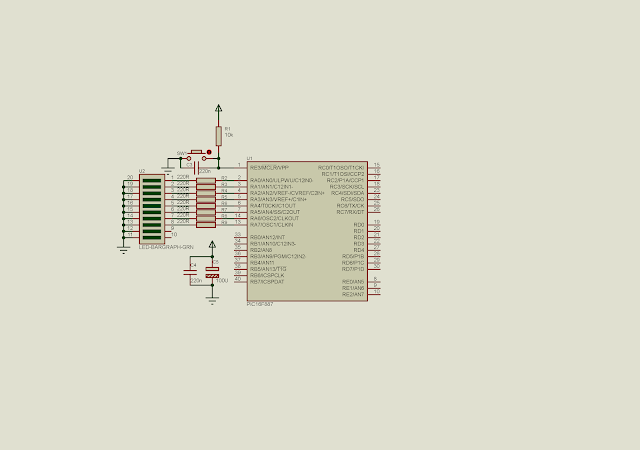
In this example, I use the internal selective RC oscillator of PIC16F887. PortA used for digital output connects to LEDs
 |
| Schematic diagram. All eight bit of PortA used for digital output. RA6 and RA7 connect to LEDs, as a result of using the internal RC oscillator with no clock out option. |
 |
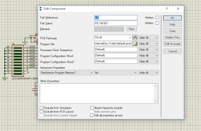
| PIC16F887 configuration setting in the Edit Component Window. |
Source code is written in XC8.
#include<xc.h>
// PIC16F887 Configuration Bit Settings
// CONFIG1
#pragma config FOSC = INTRC_NOCLKOUT
#pragma config WDTE = OFF
#pragma config PWRTE = OFF
#pragma config MCLRE = ON
#pragma config CP = OFF
#pragma config CPD = OFF
#pragma config BOREN = ON
#pragma config IESO = ON
#pragma config FCMEN = ON
#pragma config LVP = ON
// CONFIG2
#pragma config BOR4V = BOR40V
#pragma config WRT = OFF
#define _XTAL_FREQ 8000000
void selectOsc(int FREQ){
    /*Use internal clock*/
    SCS=1;
    switch(FREQ){
        /**  8 Mhz*/
        case 8:
            OSCCONbits.IRCF=0x07;
            break;
        /*4 MHz*/
        case 4:
            OSCCONbits.IRCF=0x06;
            break;
        /*2 MHz*/
        case 2:
            OSCCONbits.IRCF=0x05;
            break;
        /*1 MHz*/
        case 1:
            OSCCONbits.IRCF=0x04;
            break;
        /*500 kHz*/
        case 500:
            OSCCONbits.IRCF=0x03;
            break;
        /*250 kHz*/
        case 250:
            OSCCONbits.IRCF=0x02;
            break;
        /*125 kHz*/
        case 125:
            OSCCONbits.IRCF=0x01;
            break;
        /*31 kHz*/
        case 31:
            OSCCONbits.IRCF=0x00;
            break;
        /*If no match set 4 MHz*/
        default:
            OSCCONbits.IRCF=0x06;
            break;
    }
}
void main(void){
    /*select 8 MHz oscillator*/
    selectOsc(8);
    /*clear PortA*/
    PORTA=0x00;
    /*set PortA to output*/
    TRISA=0x00;
    /*clear analog inputs*/
    ANSEL=0x00;
    while(1){
        PORTA=0x00;
        __delay_ms(1000);
        PORTA=0xFF;
        __delay_ms(1000);
    }
}
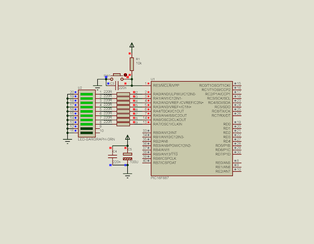
A screen shot of the simulating program.
 |
| A screen shot of the simulating program while PORTA outputs High. |
No comments:
Post a Comment