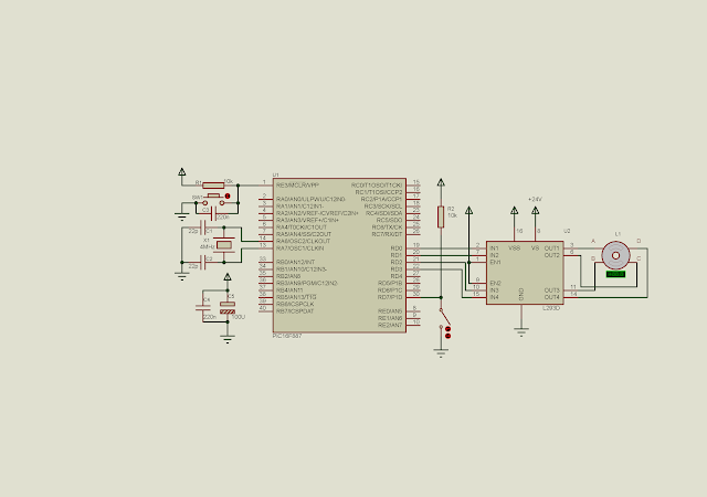
In this example, I use PIC16F887 to control the bipolar stepper motor speed and direction. The direction is determined by a switch connects to RD7.
 |
| Schematic diagram. Pin RD0 to RD3 drive the bipolar stepper motor. Pin RD7 set the stepping direction. We assume that the motor working voltage is 24 V. |
Source code is written in XC8.
#include<xc.h>
// PIC16F887 Configuration Bit Settings
// CONFIG1
#pragma config FOSC = XT
#pragma config WDTE = OFF
#pragma config PWRTE = OFF
#pragma config MCLRE = ON
#pragma config CP = OFF
#pragma config CPD = OFF
#pragma config BOREN = ON
#pragma config IESO = ON
#pragma config FCMEN = ON
#pragma config LVP = ON
// CONFIG2
#pragma config BOR4V = BOR40V
#pragma config WRT = OFF
#define _XTAL_FREQ 4000000
#define stepTime 100
//clock wise stepping
void stepCW(){
 PORTD=0b00001100;
 __delay_ms(stepTime);
 PORTD=0b00000110;
 __delay_ms(stepTime);
 PORTD=0b00000011;
 __delay_ms(stepTime);
 PORTD=0b00001001;
 __delay_ms(stepTime);
}
//counter clock wise stepping
void stepCCW(){
 PORTD=0b00001001;
 __delay_ms(stepTime);
 PORTD=0b00000011;
 __delay_ms(stepTime);
 PORTD=0b00000110;
 __delay_ms(stepTime);
 PORTD=0b00001100;
 __delay_ms(stepTime);
}
void main(){
    /*Clear PortD*/
    PORTD=0x00;
    /*RD7 input*/
    TRISD=0x80;
    while(1){
        if(RD7==0) stepCCW();
        else stepCW();
    }
}
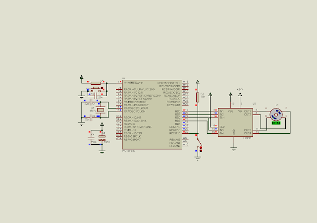
Let see the screen shot of the testing program.
 |
| A screen shot of the simulation program. |
No comments:
Post a Comment