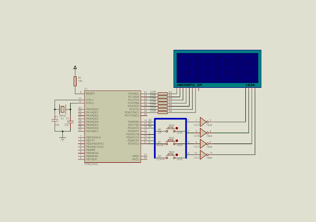
The program process is describing as follow:
- A four-digit multiplexed SSD display activated by timer 0 interrupt. Each digit is activated within 5 milli seconds period. The period created by timer 0 ISR.
- Three keys, up counter , reset counter and down counter are activated for every 200 milli seconds. Again this 150 milli seconds period generated by timer 0 ISR.
I do not describe the core programming of timer 0 here since I have done it in the previous post.
The C source codes is here.
#include <avr/io.h>
#include "avr/interrupt.h"
#define upButton ((PIND&0x01)==0)
#define resetButton ((PIND&0x02)==0)
#define downButton  ((PIND&0x04)==0)
/*System clock ticks for SSDs*/
unsigned char ssdTick=0,digit=0;
/*System clock ticks for keys*/
unsigned int found1=0,found2=0,found3=0;
unsigned int pressedCounter=1234;
void display(void){
 unsigned char patterns[16]={0x3F,0x06,0x5B,0x4F,0x66,0x6D,0x7D,
 0x07,0x7F,0x6F,0x77,0x7C,0x39,0x5E,0x79,0x71};
 switch(digit){
  case 1:
   PORTD=0x07;
   PORTC=patterns[pressedCounter/1000];
   PORTD=0x17;
   break;
  case 2:
   PORTD=0x07;
   PORTC=patterns[(pressedCounter%1000)/100];
   PORTD=0x27;
   break;
  case 3:
   PORTD=0x07;
   PORTC=patterns[(pressedCounter%100)/10];
   PORTD=0x47;
   break;
  case 4:
   PORTD=0x07;
   PORTC=patterns[pressedCounter%10];
   PORTD=0x87;
   break;
  case 5:
   digit=0;
   break;
 }
}
void buttonScan(){
 if (found1>=200)
 {
  if(upButton)
   if(pressedCounter<10000)
    pressedCounter+=1;
  found1=0;
 }
 if (found2>=200)
 {
  if(resetButton)
   pressedCounter=0;
  found2=0;
 }
 if (found3>=200)
 {
  if(downButton)
   if(pressedCounter>0)
    pressedCounter-=1;
  found3=0;
 }
}
int main(void)
{
 //Set PortC to Output
 DDRC=0xFF;
 //Clear PortC
 PORTC=0x00;
 DDRD=0xF8;
 PORTD=0x07;
 PORTC=0x00;
 //Set 1:256 prescaler
 TCCR0=0x04;
 //Clear overflow flag
 TIFR=0x01;
 //Enable Timer 0 interrupt
 TIMSK=0x01;
 //set global interrupt
 sei();
 while (1)
 {
  display();
  buttonScan();
 }
}
ISR(TIMER0_OVF_vect){
  //Load -16 to make 1 mS interrupt time
 TCNT0=-16;
 ssdTick+=1;
 //increase counters for SSD
 if(ssdTick>=5){
  digit+=1;
  ssdTick=0;
 }
 found3+=1;
 found2+=1;
 found1+=1;
 //Clear Flag
 TIFR=0x01;
}
Back to main tutorial page ATMega32 tutorials in C with Atmel Studio 7.

No comments:
Post a Comment