728x90

Wednesday, May 27, 2020

Using Timer 0 Of PIC16F887 To Make A Retentive Timer Low

Pressing a button could make noise disturbing the MCU digital input. Noise produced by internal contact of the switching button. We can eliminate noise using many methods:

  • using an S-R flip flop
  • using a passive low pass filter
  • using a software delay in the program

With a built-in timer of MCU, we can eliminate the noise and limit the time out of button pressing duration.

In this example, I use timer 0 to counter the duration of a button being pressed. The minimum duration is three seconds. If it's pressed shorter than three seconds, it's ignored.


Any calculation relates to timer 0 interrupt is skipped here, due to the repeating  in the previous post.


How to detect a long duration pressing using timer 0
Schematic diagram. RD0 and RD1 connect to buttons. RD4 and RD5 connect to
two output LEDs. If any button pressing take longer than three seconds, its
corresponding LED will toggle. Otherwise it will be ignored.

Source code is here:

#include "xc.h"
// PIC16F887 Configuration Bit Settings
// CONFIG1
#pragma config FOSC = XT
#pragma config WDTE = OFF
#pragma config PWRTE = OFF
#pragma config MCLRE = ON
#pragma config CP = OFF
#pragma config CPD = OFF
#pragma config BOREN = ON
#pragma config IESO = ON
#pragma config FCMEN = ON
#pragma config LVP = OFF
// CONFIG2
#pragma config BOR4V = BOR40V
#pragma config WRT = OFF
unsigned char cnt_0=0;
unsigned char cnt_1=0;
void main(){
    PORTD=0x00;
    TRISD=0x0F;
    T0CS=0;
    PSA=0;
    T0IE=1;
    GIE=1;
    T0IF=0;
    TMR0=0;
    while(1){
        /*Check RD0*/
        if(RD0==0){
            cnt_1=0;
            while(RD0==0){
                /*if the press durations
                 is greater than 3 minutes*/
                if(cnt_1>9){
                RD4^=1;
                break;
                }
            }
        }
        /*Check RD1*/
        if(RD1==0){
            cnt_1=0;
            /*if the press durations
             is greater than 3 minutes*/
            while(RD1==0){
                if(cnt_1>9){
                RD5^=1;
                break;
                }
            }
        }
    }
}
void interrupt _ISR(void){
    if(T0IF){
        cnt_0+=1;
        T0IF=0;
    }
    /*325 milli seconds*/
    if(cnt_0>=5){
        cnt_0=0;
        cnt_1+=1;
    }
}


Using timer 0 and PortB interrupt on change to make a digital clock

We have already about digital input output, and timer 0 with their interrupt capabilities. Now we combine those stuffs together making a real time adjustable digital clock.

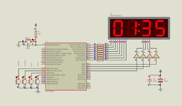
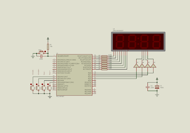
I use PortB interrupt on change to adjust minutes and hours. Timer 0 overflow interrupt makes a precise timing ticks. It create a one millisecond counting and schedule the SSD. SSD made up of four digits. Each digit turns on for 10 milli second period. The overall time of SSD takes about 40 milli seconds.

Using timer 0 and PortB interrupt on change to make a digital clock
Schematic diagram. PortB create an interrupt on change to adjust minutes and hours.
PortC and PortD displays the timing to SSD. The SSD is common anode. We can use
common cathode data with inverting. 

Source code is here.

#include "xc.h"
// PIC16F887 Configuration Bit Settings
// CONFIG1
#pragma config FOSC = XT
#pragma config WDTE = OFF
#pragma config PWRTE = OFF
#pragma config MCLRE = ON
#pragma config CP = OFF
#pragma config CPD = OFF
#pragma config BOREN = ON
#pragma config IESO = ON
#pragma config FCMEN = ON
#pragma config LVP = OFF
// CONFIG2
#pragma config BOR4V = BOR40V
#pragma config WRT = OFF
unsigned int cnt_0=0;
unsigned int cnt_1=0;
unsigned int cnt_minute=0;
unsigned int oneSecond=0;
unsigned int milliCount=0;
unsigned int _minutes=0;
unsigned int _hours=0;
void ssdOut(void){
 static unsigned char dot=0;
 unsigned char ssd[16]={0x3F,0x06,0x5B,0x4F,0x66,0x6D,0x7D,
 0x07,0x7F,0x6F,0x77,0x7C,0x39,0x5E,0x79,0x71};
 if(milliCount>=1000){
        oneSecond+=1;
        milliCount=0;
        dot^=0x80;      
 }
 if(oneSecond>=60){
     oneSecond=0;
     _minutes+=1;
 }
 if(_minutes>=60){
     _minutes=0;
     _hours+=1;
     if(_hours>=24) _hours=0;
 }
 switch (cnt_1){
     //Digit 4 1000's
     case 1:
        PORTD=0x00;
        PORTC=~ssd[_hours/10]^dot;
        PORTD=0x08;
        break;
     //Digit 3 100's
     case 2:
         PORTD=0x00;
         PORTC=~ssd[_hours%10]^dot;
         PORTD=0x04;
         break;
     //Digit 2 10's
     case 3:
         PORTD=0x00;
         PORTC=~ssd[_minutes/10]^dot;
         PORTD=0x02;
         break;
     //Digit 1 1's
     case 4:
         PORTD=0x00;
         PORTC=~ssd[_minutes%10]^dot;
         PORTD=0x01;
         break;
     case 5:
         cnt_1=0;
         break;
 }
}
void portSetUp(void){
    /*SSD display port setup*/
    PORTC=0x00;
    PORTD=0x00;
    TRISC=0x00;
    TRISD=0x00;
    /*PortB digital I/O and
     interrupt setup*/
    PORTB=0x00;
    TRISB=0x0F;
    ANSELH=0x00;
    nRBPU=0;
    WPUB=0x0F;
    IOCB=0x0F;
    RBIE=1;
    RBIF=0;
}
void timerSetup(void){
    T0CS=0;
    PSA=0;
    OPTION_REGbits.PS=0x01;
    T0IE=1;
    GIE=1;
    T0IF=0;
    TMR0=0;
}
void main(){
    portSetUp();
    timerSetup();
    
    while(1){
        ssdOut();
    }
}
void interrupt ISR(void){
    /*Timer 0 Flag*/
    if(T0IF){
        cnt_0+=1;
        /*one milli second tick*/
        milliCount+=1;
        T0IF=0;
    }
    /*IOCB flag*/
    if(RBIF){
        if(RB0==0){
            if(_minutes>0) _minutes-=1;
        }
        if(RB1==0){
            if(_minutes<60) _minutes+=1;
        }
        if(RB2==0){
            if(_hours>0) _hours-=1;
        }
        if(RB3==0){
            if(_hours<24) _hours+=1;
        }
        RBIF=0;
    }
    /*SSD timing*/
    if(cnt_0>10){
        cnt_1+=1;
        cnt_0=0;
    }
}

Simulation screen shot is here.
Using timer 0 and PortB interrupt on change to make a digital clock
A simulation screen shot, displaying an adjusted time while the counter tick is running.

Back to main tutorials page.


Writing an interrupt service routine for timer 0

In the previous post, I use timer 0 overflow interrupt to blink an LED. In that post I use the main program loop to test the interrupt flag. It could produce program delay due to CPU cycle time consumption.

For mid-range PIC, there's only one interrupt vector locates at 0x04 of the program memory. Using the interrupt service routine (ISR), it is very fast and no need to do it in the main program loop.

In this example, I use the ISR to increase the value of PortD at every 325 milli seconds.

C source code:
#include "xc.h"
// PIC16F887 Configuration Bit Settings
// CONFIG1
#pragma config FOSC = XT
#pragma config WDTE = OFF
#pragma config PWRTE = OFF
#pragma config MCLRE = ON
#pragma config CP = OFF
#pragma config CPD = OFF
#pragma config BOREN = ON
#pragma config IESO = ON
#pragma config FCMEN = ON
#pragma config LVP = OFF
// CONFIG2
#pragma config BOR4V = BOR40V
#pragma config WRT = OFF
unsigned char cnt_0=0;
unsigned char cnt_1=0;
void main(){
    
    PORTD=0x00;
    TRISD=0x00;
    T0CS=0;
    PSA=0;
    T0IE=1;
    GIE=1;
    T0IF=0;
    TMR0=0;
    while(1){
        PORTD=cnt_1;
    }
}
void interrupt _ISR(void){
    if(T0IF){
        cnt_0+=1;
        T0IF=0;
    }
    /*325 milli seconds*/
    if(cnt_0>=5){
        cnt_0=0;
        cnt_1+=1;
    }
}
Schematic diagram.

Writing an interrupt service routine for timer 0
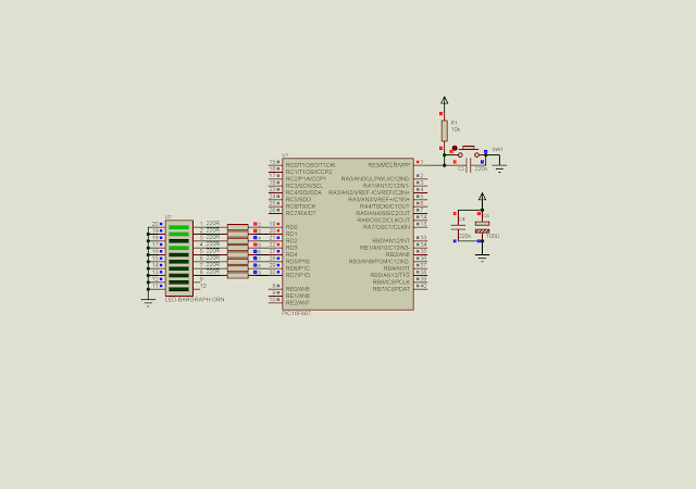
Schematic diagram while in simulating.
PortD output the counting increment ticks by
the timer 0 overflow interrupt.


Search This Blog