Overview
The SN74HC165 is an 8-bit parallel-load shift registers chip. It uses the SPI interface to shift data out from the register. This chip commonly use in keys reading in video system, printer/scanner, microwave oven, etc.
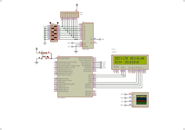 |
| Simulating Program in Proteus |
This chip is very easy to use since it's a standard logic IC. It does not require any configuration like the MCP23S17 does.
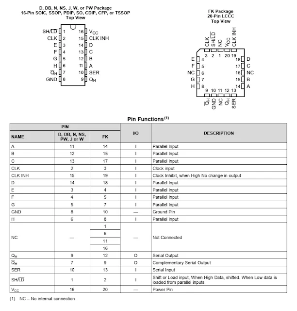 |
| Pin Configuration and Functions |
It has a Dual In Line Package (DIP) easing the electronics hobbyist prototyping. I don't have a physical chip here because it is hard to find at local store. But it has a model in Proteus VSM allowing us to simulate the behavior of this chip.
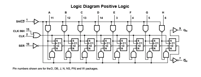 |
| Logic Diagram |
The SN74HC165 contain standard logic gates and flip flop as shown in the diagram above. It can be cascaded to make a larger registers more than 8-bit inputs.
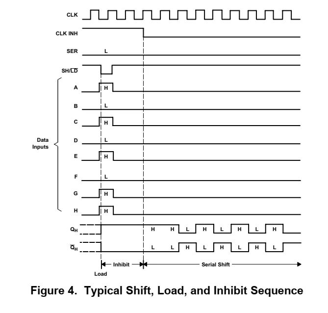 |
| Load Shift Sequence |
To use the chip the microprocessor must activate the LOAD (LD) pin from high to low transition first. It will latch the 9-bit input data into the register. Then the 8 clock cycle input via CLK (clock) pin will shift the data out at SO (serial out) pin.
The CLK INH (clock inhabit) must be pulled low to enable this chip.
PIC16F887 SPI Programming
We can use the build-in SPI module of PIC16F887 to read data from this chip. The SPI module has the following pins,
- nCS - Chip Select (RC2 or other pins)
- SCK - Serial Clock (RC3)
- SDI - Serial Data In (RC4)
- SDO - Serial Data Out (RC5)
I use the nCS pin to load data into the SN74C165 first before the data shifts out. In this example, the PIC16F887 read data from the SN74HC165. The 8-bit data will show on a 16x2 character LCD in decimal, hexadecimal and binary value.
I putted the SPI driver in one package.
The spi.h header file:
The spi.c source file:
Click here to download this example.
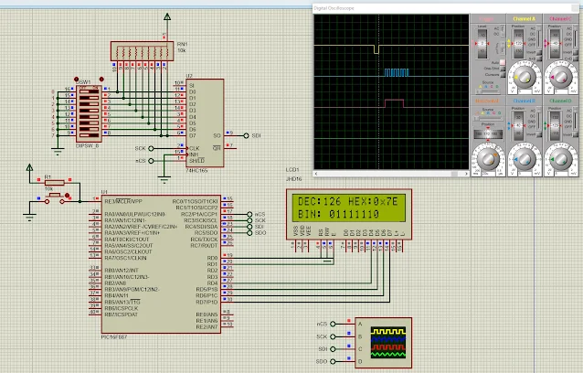 |
| Simulating Program in Proteus |
We can use the PIC16F84A with SPI bit-banging to read the data from this chip. A larger AVR chip, the ATMega32 could use a software SPI to interface to this chip.
You can see the software SPI version of this example.
No comments:
Post a Comment