The 93AA46B is an 1Kbit Microwire compatible serial EEPROM. It uses the SPI interface to communicate to the microprocessor. It memory is arranged into a 16-bit data per address, that's 64x16-bit. It can handle up to 1000000 erase/write cycles with over 200 years data retention.
 |
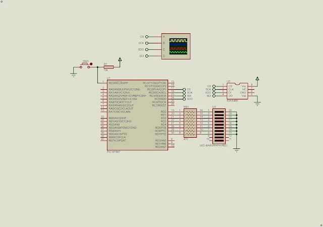
| Schematic Diagram |
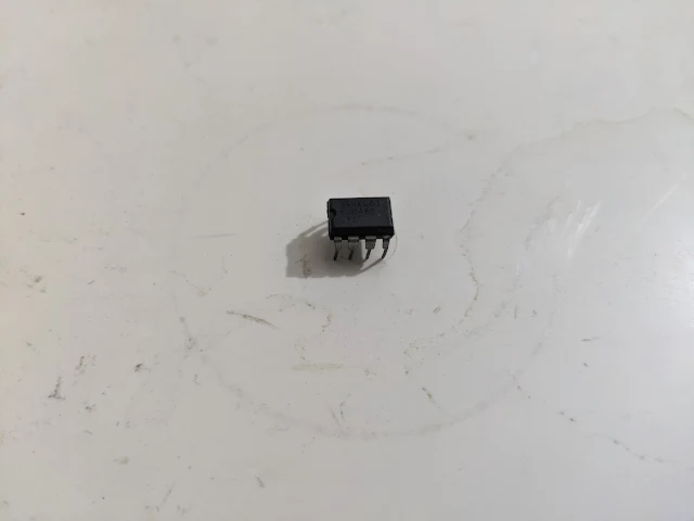
This chip also has a Dual In Line Package (DIP-8) allow the hobbyist to prototype the circuit easily.
 |
| Pin Diagram and Description |
The ORG pin does not exist for the 93AA46B. So we must left it unconnected. It has the following commands to read, write, erase, etc.
 |
| SPI Commands |
The SB and Opcode is a one byte data. For example, the READ command is 0b110 or 0x06.
 |
| 93C46B DIP-8 Package |
The Address is one byte data. The data is 16-bit wide, or two bytes.
For example, to erase a specific memory location the controller does the following sequence,
- Raise the Chip Select (CS) pin high
- Send the ERASE command 0x07
- Send the Address
- Lower the Chip Select (CS) pin.
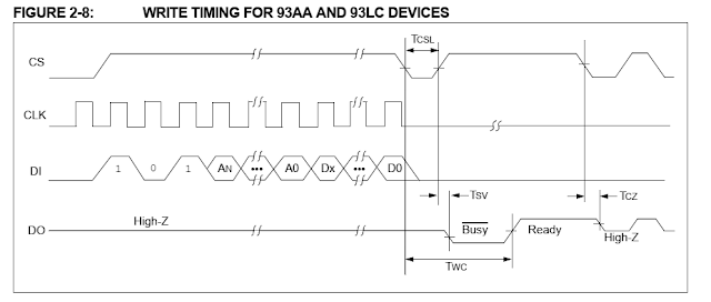
Before we can write data to any address we must enable the EWEN(Erase Write Enable) command first. So
- Raise the CS pin
- Send the EWEN command 0x04
- Send the data 0xC0
- Lower the CS pin
Then we can proceed the data writing command. That's,
- Raise the CS pin
- Send the WRITE command 0x05
- Send the the memory address
- Send the 16-bit data (2 bytes)
- Lower the CS pin
To read from any memory address we must do the following sequence,
- Raise the CS pin
- Send the READ command 0x06
- Send the address of the memory
- Receive the two-byte (16-bit) data packages
- Lower the CS pin
 |
| The EWEN Timing Diagram |
In this example, the PIC16F887 write and read data from the 93AA46B SPI EEPROM chip. The data will show on PORTD.
I use the bit-banging SPI to process the data transfer and receive. However I use only one byte of its 16-bit data.
 |
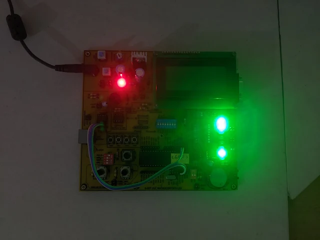
| PIC16F887 Prototyping Board |
I use my own PIC16F887 Prototyping Board to test this program. Click here to download its source file.
No comments:
Post a Comment