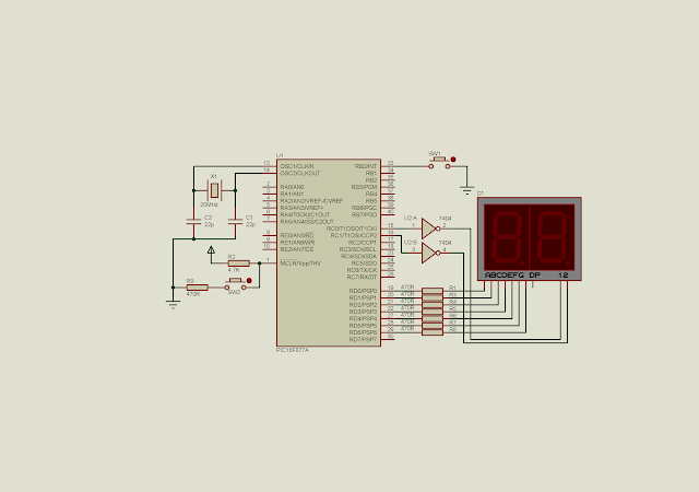
I have showed an example of Timer 0 interrupt programming of PIC16F877A in an earlier post. Here I use timer 0 interrupt to drive a multiplexing seven-segments display. This method is very effective in any application that contain many tasks polling.
In this example, timer 0 overflow interrupt will create a timer tick around 2.56 milliseconds. This timer tick regularly activate each digits of the multiplexing seven-segment display.
Sample program |
In main program loop, the program just check whenever the button is press. It will need to wait until the button is released until it increase the press counter.
The display shows the counting content up to 60 before it reset to 0. The display show the counting content with any flickering due to the long-time button pressing.
Source Code:
/* * PIC16F877A Timer0 Interrupt and multiplexing * display example */ #include <xc.h> #include "config.h" //RB0 input button #define SW1 RB0 unsigned int cnt=0,cntPress=0; //Common cathode display pattern char cCathode[10]={0x3F,0x06,0x5B,0x4F,0x66,0x6D,0x7D,0x07,0x7F,0x6F}; int main(void){ //Clear PortD PORTD=0x00; //Clear PortC PORTC=0x00; //Clear PortB PORTB=0x00; //PortD output TRISD=0x00; //PortC output TRISC=0x00; //RB0 is input TRISB0=1; //Turn on PortB Pullup resistors nRBPU=0; //select internal instruction cycle clock T0CS=0; //Select timer 0 prescaler PSA=0; //select 1:256 prescaler OPTION_REGbits.PS=0x07; //Enable timer0 interrupt T0IE=1; //Enable interrupt GIE=1; T0IF=0; //Clear Timer 0 TMR0=0; while(1){ //Switch pressing count if(SW1==0){ //Wait until it's release while(SW1==0); cntPress+=1; } if(cntPress>=60) cntPress=0; } } //Timer0 Interrupt Service Routine - ISR void interrupt _T0_ISR(void){ if(T0IF){ //increase counter cnt+=1; //make a 10 mS time TMR0=-50; //Clear Flag T0IF=0; } switch(cnt){ case 1: PORTC=0x00; PORTD=cCathode[cntPress/10]; RC0=1; break; case 2: PORTC=0x00; PORTD=cCathode[cntPress%10]; RC1=1; break; case 3: cnt=0; break; } }
Configuration bits:
// PIC16F877A Configuration Bit Settings // CONFIG // Oscillator Selection bits (HS oscillator) #pragma config FOSC = HS // Watchdog Timer Enable bit (WDT disabled) #pragma config WDTE = OFF // Power-up Timer Enable bit (PWRT disabled) #pragma config PWRTE = OFF // Brown-out Reset Enable bit (BOR enabled) #pragma config BOREN = ON /* * Low-Voltage (Single-Supply) In-Circuit Serial * Programming Enable bit (RB3 is digital I/O, * HV on MCLR must be used for programming) */ #pragma config LVP = OFF /* * Data EEPROM Memory Code Protection bit * (Data EEPROM code protection off) */ #pragma config CPD = OFF /* * Flash Program Memory Write Enable bits * (Write protection off; all program memory * may be written to by EECON control) */ #pragma config WRT = OFF /* * Flash Program Memory Code Protection bit * (Code protection off) */ #pragma config CP = OFF
Schematic:
Using Timer0 Overflow Interrupt of PIC16F877A to Drive Multiplexing Display |
Click here to download source file.