In previous post, I introduced about Timer 0 Programming of PIC16F877A. Timer 0 can generate interrupt, whenever its 8-bit timer register TMR0 overflow from 0xFF to 0x00. Its interrupt flag T0IF (timer 0 interrupt flag) will be set.
However the programmer need to configure their relevant registers properly, before the interrupt can be used. There are three fundamental registers that relate to timer 0 operation, and interrupt programming.
 |
| Running program on breadboard |
 |
| REGISTERS ASSOCIATED WITH TIMER0 |
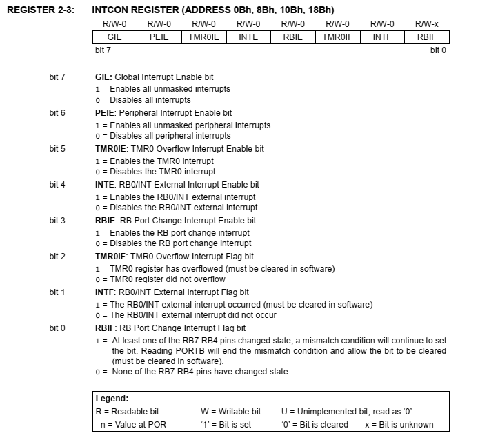
Timer 0 prescaler must be configure to an appropriate value by the programmer, to obtain a prescribed result. Interrupt Control Register (INTCON) contains the interrupt setting of timer 0, and other interrupt sources.
 |
| INTCON REGISTER (ADDRESS 0Bh, 8Bh, 10Bh, 18Bh) |
Programmer will need to set the TMR0 Overflow Interrupt Flag bit first. Then the Global Interrupt Enable bit (GIE) must be set. TMR0 register must be clear (0x00) after finishing the timer 0 interrupt configuration settings.
In the interrupt service routine - ISR the programmer need to test the T0IF flag, and write the corresponding codes for what to do. Optionally, the TMR0 register must be pre-load with any value. Finally, the T0IF flag must be clear to make the interrupt triggers again.
In this example, the result is just like the one in previous post. An output LED toggle for every 500 mS, yielding an output frequency around 1 Hz. However the main program loop is just idle in "while" loop.
Source code:
Configuration settings:
Schematic Diagram:
 |
| Schematic Diagram |
Click here to download source file.
No comments:
Post a Comment