Introduction
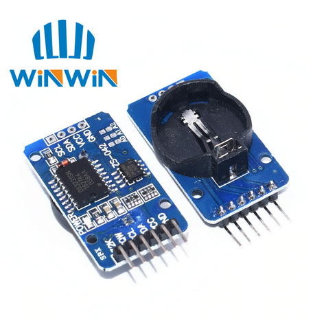
An electronics digital clock usually equipped with a Real Time Clock (RTC) IC – for example DS3231 RTC. However we can build a non-complex one’s using internal timer of a microcontroller. This feature doesn’t have time keeping as RTC chip. It lost all its previous timing when it’s powered off.
 |
| A commercial sample of DS3231 RTC module from Ali Express |
Digital Clock made from Timer0
Timer0 module creates a precise timing when it’s running in timer mode. Timing tick period is configurable by user. A a simple programming example we start with showing timing data on a multiplexing display.
Hardware Preparation
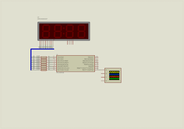
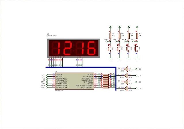
Main controller powered by PIC16F818 microcontroller. It’s suitable for this simple project. Display is assumed to be a dedicated digital clock display in multiplexing type. It’s common anode type as there’s no other option.
 |
| Schematic diagram |
We don’t use external reset on RA5 pin. Higher nibble of Port A is reserved for digital inputs. These four inputs are minute and second adjustment. Controller clocks from its internal 8MHz oscillator.
Program Preparation
Blueprint of this digital clock project is Timer0 interrupt. Timer0 clock source is internal microcontroller clock with 1:2 prescaler. Timer0 interrupt creates timing tick of 100us. Each time the interrupt occurs Timer0 register is preloaded with 100 to get this timing interval.
Display
Multiplexing display is activated for every 5ms for each digit. A counting register schedule this task. It runs from 0 to 20ms before it rolls back to 0.
Buttons
Four input buttons are,
- Increasing minute on RA4
- Decreasing minute on RA5
- Increasing second on RA6
- Increasing second on RA7
Each button pressing will be accept by controller after 200ms. This 200ms timer tick create by buttonTime counting variable. Whenever any button is pressed time adjustment is made, and this time counting variable is reset to 0.
Timer0 Interrupt
ISR of PIC16F818 keeps track of Timer0 overflow interrupt. Each time interrupt occurs Timer0 Register (TMR0) preload with value of 100 to gain a 100us timer tick.
void interrupt _myISR(void){
/*Check Timer0 Interrupt Flag*/
if(TMR0IE&&TMR0IF){
TMR0=-100;
t0Counter+=1;
micro_100+=1;
TMR0IF=0;
}
}
There are two additional timer variable to multiplex display and create a one millisecond time.
Programming
Overall XC8 program made of about 168 lines of code including white spaces and comments.
* PIC16F818 Simple 7-Segments
* multiplexing display clock
*/
#include <xc.h>
#include "pic16f818Config.h"
#define MININC RA4
#define MINDEC RA5
#define SECINC RA6
#define SECDEC RA7
#define maxPress 200
void ioInit(void);
void timer0Init(void);
void ssdDisplay(void);
void timeAdjust(void);
unsigned long getOneSecond(void);
unsigned long t0Counter=0;
unsigned long micro_100=0;
unsigned char oneSecond=0;
unsigned char buttonTime=0;
unsigned char minute=12;
char blinker=0xFF;
void main(void){
unsigned long oneSecond=0;
ioInit();
timer0Init();
while(1){
oneSecond=getOneSecond();
timeAdjust();
ssdDisplay();
}
}
/*Digital IO and Clock Set Up*/
void ioInit(void){
/*Clear IO*/
PORTA=0x00;
PORTB=0x00;
/*Port A higher nibble is digital input*/
TRISA=0xF0;
/*Port B as output*/
TRISB=0x00;
/*Turn on Pull Up Resistors*/
nRBPU=0;
/*Clear Analog function on Port A*/
ADCON1=0x06;
/*Set up internal oscillator*/
OSCCONbits.IRCF=0x07;
}
/*Timer 0 Set Up Section*/
void timer0Init(void){
/*Select internal timer mode*/
T0CS=0;
/*Select Timer0 Prescaler*/
PSA=0;
/*Select 1:2 Timer0 Rate*/
OPTION_REGbits.PS=0x00;
/*Enable Timer0 Interrupt*/
TMR0IE=1;
/*Turn On Global Interrupt*/
GIE=1;
/*Clear Timer0 Interrupt Flag*/
TMR0IF=0;
/*Clear Timer0*/
TMR0=0;
}
/*Get one second routine*/
unsigned long getOneSecond(void){
if(t0Counter>=10000){
oneSecond+=1;
blinker^=0x80;
blinker|=0b01111111;
t0Counter=0;
}
return oneSecond;
}
/*Multiplexing Display Routine*/
void ssdDisplay(void){
/*common anode display pattern*/
char anodePattern[16]={192,249,164,176,153,146,130,248,128,144,136,131,198,161,134,142};
static unsigned char oneMilli=0;
if(micro_100>=10){
oneMilli+=1;
micro_100=0;
buttonTime+=1;
}
if(oneMilli>20){
oneMilli=0;
}
if(oneSecond>=60){
oneSecond=0;
minute+=1;
if(minute>=60) minute=0;
}
/*Driving multiplexing display*/
switch(oneMilli){
case 0:
PORTA=0x00;
PORTB=anodePattern[oneSecond%10]&blinker;
PORTA=0x08;
break;
case 5:
PORTA=0x00;
PORTB=anodePattern[oneSecond/10]&blinker;
PORTA=0x04;
break;
case 10:
PORTA=0x00;
PORTB=anodePattern[minute%10]&blinker;
PORTA=0x02;
break;
case 15:
PORTA=0x00;
PORTB=anodePattern[minute/10]&blinker;
PORTA=0x01;
break;
}
}
/*Adjusting Time*/
void timeAdjust(void){
/*Checking digital inputs*/
if(buttonTime>=maxPress){
if(MININC==0){
if(minute<60) minute++;
buttonTime=0;
}
if(MINDEC==0){
if(minute>0) minute--;
buttonTime=0;
}
if(SECINC==0){
if(oneSecond<60) oneSecond++;
buttonTime=0;
}
if(SECDEC==0){
if(oneSecond>0) oneSecond--;
buttonTime=0;
}
}
}
/*Interrupt Service Routine*/
void interrupt _myISR(void){
/*Check Timer0 Interrupt Flag*/
if(TMR0IE&&TMR0IF){
TMR0=-100;
t0Counter+=1;
micro_100+=1;
TMR0IF=0;
}
}
PIC16F818 C configuration settings store in “pic16f818Config.h” file.
// CONFIG
#pragma config FOSC = INTOSCIO // Oscillator Selection bits (INTRC oscillator; port I/O function on both RA6/OSC2/CLKO pin and RA7/OSC1/CLKI pin)
#pragma config WDTE = OFF // Watchdog Timer Enable bit (WDT disabled)
#pragma config PWRTE = OFF // Power-up Timer Enable bit (PWRT disabled)
#pragma config MCLRE = OFF // RA5/MCLR/VPP Pin Function Select bit (RA5/MCLR/VPP pin function is MCLR)
#pragma config BOREN = ON // Brown-out Reset Enable bit (BOR enabled)
#pragma config LVP = OFF // Low-Voltage Programming Enable bit (RB3/PGM pin has digital I/O function, HV on MCLR must be used for programming)
#pragma config CPD = OFF // Data EE Memory Code Protection bit (Code protection off)
#pragma config WRT = OFF // Flash Program Memory Write Enable bits (Write protection off)
#pragma config CCPMX = RB2 // CCP1 Pin Selection bit (CCP1 function on RB2)
#pragma config CP = OFF // Flash Program Memory Code Protection bit (Code protection off)
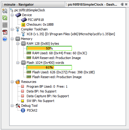
Click here to download source file. Its statistic shown below.
 |
| Dashboard in MPLABX |

What an insightful and well-written article! Your content is incredibly engaging and offers a fresh perspective on the topic. I appreciate the depth of information and the practical tips that readers can easily implement. It's clear that a lot of research and thought went into crafting this post, making it not just informative but also a pleasure to read. Keep up the great work—looking forward to reading more of your content!
ReplyDeleteProgrammable Timers And Oscillators Enrgtech