A Short Detail of Timer/Counter1
Timer/Counter1 module of Atmega32 is superior to Timer/Counter0. It has some advanced features over the previous one's:
- 16-bit wide made of two 8-bit registers
- Input capture mode
- Improved PWM mode
- Four interrupt source
It has two Timer/Counter registers working as a pair of two 8-bit low and high register - TCNT1H and TCNT1L. As a result the Timer/Counter registers is 16-bit in total.
 |
| Timer/Counter1 Register -TCNT1H and TCNT1L |
There are more additional Timer/Counter control registers and interrupt flag. But we only list some in-use registers in this post.
Timer/Counter1 Control Register B (TCCR1B) contain functions setting of this module working in timer mode.
 |
| Timer/Counter1 Control Register B |
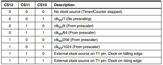
Clock Select bit (CS12:10) of this register set the clock source of Timer/Counter1.
 |
| Timer/Counter1 Clock Select bit |
Interrupt occurs at the maximum counting of this 16-bit Timer/Counter at 65536. Then the Timer/Counter1 overflow interrupt flag (TOV1) is set.
 |
| Timer/Counter Interrupt Flag Register - TIFR |
Programming Timer/Counter1 in Timer Mode
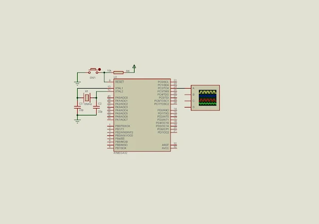
In this Timer/Counter1 timer mode example, the program configure this module to make a timer tick of 262ms. This timer tick is a result of its interrupt at overflow. At the interrupt time PC2 of Port C toggles.
 |
| Schematic diagram of this example post |
We have a calculation below.
Microcontroller instruction cycle with its 16MHz clock frequency is,
1/16000000 = 62.5ns
With a clock selection of Clk/64 we get,
64*62.5ns = 4us.
Sixteen bit Timer/Counter1 register counts up to 65536 value to generate the interrupt flag. The duration before the TOV1 is set is,
65536*4us = 262ms.
For every 262ms PC2 toggles an output LED.
* timer_1_example.c
*
* Created: 12/19/2020 8:57:35 PM
* Author : aki-technical
*/
#include <avr/io.h>
int main(void)
{
/*Select Timer Mode, CLK/64*/
TCCR1B=(1<<CS11)|(1<<CS10);
/*PC2 Output*/
DDRC=(1<<2);
/*Clear Timer Overflow Flag 1*/
TIFR=(1<<TOV1);
while (1)
{
/*Check for overflow*/
if (TIFR&(1<<TOV1))
{
/*Clear this flag*/
TIFR=(1<<TOV1);
/*Toggle PB2*/
PORTC^=0x04;
}
}
}
Let see the simulation result in software.
 |
| Simulation result in Proteus |
Click here to download this example file.
No comments:
Post a Comment