However in this section I don't want to discuss all this interrupt capabilities. Here I show only how to program the USART interrupt on the receiver side.
It's similar to the introductory post, but here I use the receiver interrupt to get the data from the buffer. Using the interrupt it is more time effective. We can see this advantage just a large program contain a lot of working codes.
We must do this setting to get the USART interrupt working.
- Enable the RX Complete Interrupt Enable (RXCIE) of the UCSRC register.
- Enable the Global Interrupt of the SREG register
- Write the Interrupt Service Routine (ISR) for the USART receiver interrupt.
The interrupt vector of the USART receiver complete is USART_RXC_vect . Within this ISR the programmer must read the data from the UDR, then clear the USART Receive Complete (RXC).
Let look at this example.
/*
* uart_interrupt.c
*
* Created: 9/30/2020 9:14:17 PM
* Author : aki-technical
*/
#include <avr/io.h>
#define F_CPU 16000000UL
#include <util/delay.h>
#include <avr/interrupt.h>
void uartInit(unsigned long baud){
unsigned int UBRR;
/*Baud rate calculator*/
UBRR=(F_CPU/(16*baud))-1;
UBRRH=(unsigned char)(UBRR>>8);
UBRRL=(unsigned char)UBRR;
/*Enable the transmitter and receiver with receiver
complete interrupt*/
UCSRB=(1<<RXCIE)|(1<<RXEN)|(1<<TXEN);
/*asynchronous mode, 8-bit, 1-stop bit*/
UCSRC=(1<<URSEL)|(1<<UCSZ1)|(1<<UCSZ0);
sei();
}
void uartTransmit(unsigned char data){
/*Stay here until the buffer is empty*/
while(!(UCSRA&(1<<UDRE)));
/*Put the data into the buffer*/
UDR=data;
}
void uartString(unsigned char *data){
while(*data) uartTransmit(*data++);
}
char rcvData=0;
int main(void)
{
DDRC=0xFF;
uartInit(9600);
uartString("USART Receiver Interrupt Example.\r");
while (1)
{
PORTC=rcvData;
}
}
/*Interrupt Vector for the USART*/
ISR(USART_RXC_vect){
/*Read the data from buffer*/
rcvData=UDR;
/*Clear the interrupt flag*/
UCSRA|=(1<<RXC);
}
Click here to download the zip file of this working example.
 |
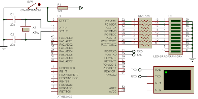
| Schematic Diagram |
PORTC displays the received data from the terminal.
If you want a standard PCB for ATMega32 micro-controller, you can order my AVR Microcontroller project from PCBWay with a reasonable price. Click here to get a free $5 credit for new account.
No comments:
Post a Comment