Wednesday, September 30, 2020

AVR ATMega32 USART Receiver Interrupt Programming Example

We have already discussed about the USART module of the ATMega32 with some details and its programming example in AVR C. The transmitter interrupt is occur whenever the transmitter has complete the data transfer. It set the USART Transmit Complete (TXC). Similarly, the receiver interrupt is occur whenever the it has complete the data reception. It set the USART Receiver Complete (RXC).

However in this section I don't want to discuss all this interrupt capabilities. Here I show only how to program the USART interrupt on the receiver side.

It's similar to the introductory post, but here I use the receiver interrupt to get the data from the buffer. Using the interrupt it is more time effective. We can see this advantage just a large program contain a lot of working codes.

We must do this setting to get the USART interrupt working.
  1. Enable the RX Complete Interrupt Enable (RXCIE) of the UCSRC register.
  2. Enable the Global Interrupt of the SREG register
  3. Write the Interrupt Service Routine (ISR) for the USART receiver interrupt.
The interrupt vector of the USART receiver complete is USART_RXC_vect . Within this ISR the programmer must read the data from the UDR, then clear the USART Receive Complete (RXC).

Let look at this example.

/*
 * uart_interrupt.c
 *
 * Created: 9/30/2020 9:14:17 PM
 * Author : aki-technical
 */ 

#include <avr/io.h>

#define F_CPU 16000000UL
#include <util/delay.h>
#include <avr/interrupt.h>

void uartInit(unsigned long baud){
unsigned int UBRR;
/*Baud rate calculator*/
UBRR=(F_CPU/(16*baud))-1;
UBRRH=(unsigned char)(UBRR>>8);
UBRRL=(unsigned char)UBRR;
/*Enable the transmitter and receiver with receiver
complete interrupt*/
UCSRB=(1<<RXCIE)|(1<<RXEN)|(1<<TXEN);
/*asynchronous mode, 8-bit, 1-stop bit*/
UCSRC=(1<<URSEL)|(1<<UCSZ1)|(1<<UCSZ0);
sei();
}

void uartTransmit(unsigned char data){
/*Stay here until the buffer is empty*/
while(!(UCSRA&(1<<UDRE)));
/*Put the data into the buffer*/
UDR=data;
}

void uartString(unsigned char *data){
while(*data) uartTransmit(*data++);
}

char rcvData=0;

int main(void)
{
DDRC=0xFF;
uartInit(9600);
uartString("USART Receiver Interrupt Example.\r");
while (1)
{
PORTC=rcvData;
}
}

/*Interrupt Vector for the USART*/
ISR(USART_RXC_vect){
/*Read the data from buffer*/
rcvData=UDR;
/*Clear the interrupt flag*/
UCSRA|=(1<<RXC);
}

Click here to download the zip file of this working example.

AVR ATMega32 USART Receiver Interrupt Programming Example
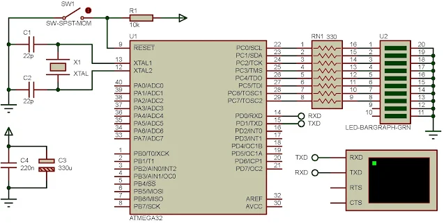
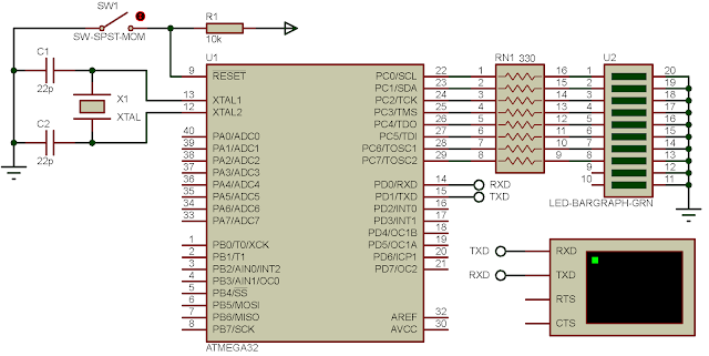
Schematic Diagram

PORTC displays the received data from the terminal.
 

If you want a standard PCB for ATMega32 micro-controller, you can order my AVR Microcontroller project from PCBWay with a reasonable price. Click here to get a free $5 credit for new account.


ATMega32 AVR USART C programming examples

In the previous post I have shown about a few details of the USART module the ATMega32 device with some working examples. Here I put some more USART examples with some AVR C programming techniques - making a condition with the received characters, and using the ANSI C string functions library.

Conditioning the receiving characters

Within this simple example, The user sends some characters to the MCU USART module via the host PC USART terminal. The MCU keeps track of the characters and store them in an array at a size of 15 characters, or any size up to the programmer. 


Whenever the user send the ENTER key ( ASCII value of 0x0D) the MCU terminates the the next character storing and send back all the previous characters back to the host PC terminal.

/*
 * uart_example_1.c
 *
 * Created: 9/30/2020 10:21:10 AM
 * Author : aki-technical
 */ 

#include <avr/io.h>

#define F_CPU 16000000UL
#include <util/delay.h>

#define uartReady UCSRA&(1<<RXC)

void uartInit(unsigned long baud){
unsigned int UBRR;
/*Baud rate calculator*/
UBRR=(F_CPU/(16*baud))-1;
UBRRH=(unsigned char)(UBRR>>8);
UBRRL=(unsigned char)UBRR;
/*Enable the transmitter and receiver*/
UCSRB=(1<<RXEN)|(1<<TXEN)|(1<<RXEN);
/*asynchronous mode, 8-bit, 1-stop bit*/
UCSRC=(1<<URSEL)|(1<<UCSZ1)|(1<<UCSZ0);
}

void uartTransmit(unsigned char data){
/*Stay here until the buffer is empty*/
while(!(UCSRA&(1<<UDRE)));
/*Put the data into the buffer*/
UDR=data;
}

char uartReceive(){
/*Wait until the buffer is full*/
while(!(UCSRA&(1<<RXC)));
/*Get the data ready to use*/
return UDR;
}

void sendText(char *txt){
while(*txt) uartTransmit(*txt++);
}


int main(void)
{
char tmp,i=0;
char txt[15];
DDRC=0xFF;
uartInit(9600);
sendText("ATMEGA32 AVR UART Example 1\n\r");
while (1)
{
/*If There is a character in the buffer*/
if (uartReady)
{
tmp=uartReceive();
PORTC=tmp;
txt[i]=tmp;
i++;
}
/*If the ENTER Key Is Presented*/
if (tmp==0x0D)
{
/*Send text back to the terminal*/
sendText(txt);
/*Clear the character storage*/
tmp='\0';
/*Clear all the texts*/
while(i>0){
txt[i]='\0';
i--;
}
}
}
}

The overall source codes of the program is a little different from the previous post, except the a few block of C code that make the conditioning the received characters.

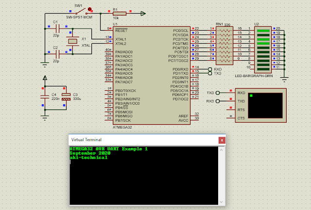
ATMega32 AVR USART examples.
schematic diagram 

I set the clock to 16 MHz to work with my own prototyping board. The output LED bar graph at PORTC indicates the present of data received.

ATMega32 AVR USART C programming examples.
A sample of this program

Click here to download the zip file of this working example.

Using the ANSI C string functions library

This example I use the string compare function from the ANSI C string library function. There are a lot of string processing functions in this library. However I pick up only one's that only required in this example. 

The string compare - strcmp()

int strcmp(char *string1,char *string2);

where,
- string1 is the first string to be compared
- string2 is the second string to be compared

This function returns:
  • less than zero if string1 is less than string2
  • greater than zero if string1 is greater than string2
  • zero if these two string are equal.
Now let move the overall processes of this example. Once the user sends the command the MCU reads the character stored in the USART buffer, and make it a string. Whenever the user enter a new line or ENTER, the MCU start process the string comparison. When the comparison is matched the MCU toggles its corresponding output pin.

Let see the source code.

/*
 * uart_example_2.c
 *
 * Created: 9/30/2020 5:34:08 PM
 * Author : aki-technical
 */ 

#include <avr/io.h>

#define F_CPU 16000000UL
#include <util/delay.h>

#include <string.h>

#define uartReady UCSRA&(1<<RXC)

void uartInit(unsigned long baud){
unsigned int UBRR;
/*Baud rate calculator*/
UBRR=(F_CPU/(16*baud))-1;
UBRRH=(unsigned char)(UBRR>>8);
UBRRL=(unsigned char)UBRR;
/*Enable the transmitter and receiver*/
UCSRB=(1<<RXEN)|(1<<TXEN)|(1<<RXEN);
/*asynchronous mode, 8-bit, 1-stop bit*/
UCSRC=(1<<URSEL)|(1<<UCSZ1)|(1<<UCSZ0);
}

void uartTransmit(unsigned char data){
/*Stay here until the buffer is empty*/
while(!(UCSRA&(1<<UDRE)));
/*Put the data into the buffer*/
UDR=data;
}

unsigned char uartReceive(void){
/*Wait until the buffer is full*/
while(!(UCSRA&(1<<RXC)));
/*Get the data ready to use*/
return UDR;
}

void sendText(char *txt){
while(*txt) uartTransmit(*txt++);
}

char tmp,i=0;
char txt[15];
/*Some string constants to compare with USART command*/
const char cmp1_on[]="rl1On\r",cmp1_off[]="rl1Off\r";
const char cmp2_on[]="rl2On\r",cmp2_off[]="rl2Off\r";
const char cmp3_on[]="rl3On\r",cmp3_off[]="rl3Off\r";
const char cmp4_on[]="rl4On\r",cmp4_off[]="rl4Off\r";
const char allOn[]="allOn\r",allOff[]="allOff\r";

void clearAll(void){
/*Clear the character storage*/
tmp='\0';
/*Clear all the texts*/
while(i>0){
txt[i]='\0';
i--;
}
}

int main(void)
{
DDRC=0xFF;
uartInit(9600);
sendText("ATMEGA32 AVR UART With C String Library Example\r");
while (1)
{
/*If There is a character in the buffer*/
if (uartReady)
{
tmp=uartReceive();
uartTransmit(tmp);
txt[i]=tmp;
i++;
}
/*ENTER or new line is 0x0D in hex*/
if(tmp=='\r'){
/*Toggling pin PC0*/
if(strcmp(txt,cmp1_on)==0){
PORTC|=(1<<0);
sendText("Relay 1 Turns On.\r");
}
else if (strcmp(txt,cmp1_off)==0){
PORTC&=~(1<<0);
sendText("Relay 1 Turns Off.\r");
}
/*Toggling pin PC1*/
if(strcmp(txt,cmp2_on)==0){
PORTC|=(1<<1);
sendText("Relay 2 Turns On.\r");
}
else if(strcmp(txt,cmp2_off)==0){
PORTC&=~(1<<1);
sendText("Relay 2 Turns Off\r");
}
/*Toggling pin PC2*/
if(strcmp(txt,cmp3_on)==0){
PORTC|=(1<<2);
sendText("Relay 3 Turns On.\r");
}
else if(strcmp(txt,cmp3_off)==0){
PORTC&=~(1<<2);
sendText("Relay 3 Turns Off\r");
}
/*Toggling pin PC3*/
if(strcmp(txt,cmp4_on)==0){
PORTC|=(1<<3);
sendText("Relay 4 Turns On.\r");
}
else if(strcmp(txt,cmp4_off)==0){
PORTC&=~(1<<3);
sendText("Relay 4 Turns Off.\r");
}
/*Overall Controls*/
if (strcmp(txt,allOn)==0)
{
PORTC=0x0F;
sendText("All relays turn on\r");
}
else if (strcmp(txt,allOff)==0)
{
PORTC=0x00;
sendText("All relays turn off\r");
}
/*Clearing all the data*/
clearAll();
}
}
}

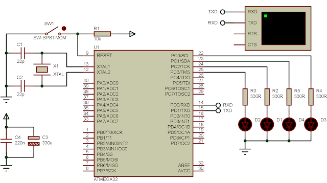
In the source code I mentioned the relay. However the output devices in schematic diagram are the LED rather than the relays.

ATMega32 AVR USART C programming examples
Schematic Diagram

Click here to download the zip file of this working example.


If you want a standard PCB for ATMega32 micro-controller, you can order my AVR Microcontroller project from PCBWay with a reasonable price. Click here to get a free $5 credit for new account.


Tuesday, September 29, 2020

ATMega32 AVR Universal Asynchronous Receiver Transmitter (UART)

Overview of AVR ATMega32 USART/UART

The Universal Synchronous/Asynchronous serial Receiver/Transmitter (USART) is a serial communication interface that communicates in either synchronous or asynchronous mode.  The Universal Asynchronous Receiver Transmitter (UART) is serial communication interface that work only in asynchronous mode. In the AVR ATMega32, this communication module is called USART, and it's fully compatible with the UART.

Here are some basic features of the module I got from the device datasheet:

  • Full duplex operation
  • Asynchronous/Synchronous operation
  • Master/Slave mode
  • Precise clock generator
  • Selectable data bits from 5 9, up to two stop bits
  • Normal or double speed
The figure below is a detailed block diagram of the USART.

ATMega32 AVR Universal Asynchronous Receiver Transmitter (UART)
The block diagram of the USART from the device vendor specification

Clock generation for the USART Baud rate

The MCU clock frequency Fosc creates the timing for the USART baud rate. The USART Baud Rate Register (UBRR) that make up to two 8-bit register creates the baud rate for this communication. It's a count down timer.

Clock generator block diagram from the device's datasheet

The Baud rate (in bits per second, bps) is BAUD in short. There are three modes of the USART operation. To find the BAUD we have the equations list below.

Relation between the BAUD and the UBRR register

The UBRR (contains the UBRRH and the UBRRL) is a 12-bit register (0 to 4095). 

The transfer rate could be twice in speed by using the double speed mode. This reduce the baud rate divisor from 16 to 8.

Frame Formats

In the serial communication one frame of data defines a character the make up of several data bits. A frame may contains of,
  • 1 start bit
  • 5, 6, 7, 8, or 9 data bits
  • no, even or odd parity bit
  • one or two stop bits
A data frame initiates by a start bit follows by many remanding bits as shown below. An idle mode keep the data line high until it's pulled low to start the data transmission.

The data frame formats of the USART

For instant the programmer select a BAUD of 9600, an 8-bit data mode, no parity bit and 1 stop bit.  

USART Registers Configurations and Operations

To initial the USART with a desired requirements we must take some register configurations in the,
  • UCSRA - USART Control and Status Register A
  • UCSRA - USART Control and Status Register B
  • UCSRC - USART Control and Status Register C
  • UBRRL and UBRRH - USART Baud Rate Registers (UBRR)
Another one's is the USART I/O data register (UDR). It's an 8-bit shift register that shift data in and out for the data transmission/reception. It cooperates with other two FIFO registers that I don't list the full details here.

USART Control and Status Register A

USART Control and Status Register A
  • Bit 7 - RXC : USART Receiver Complete
It's set whenever there's an unread data in the buffer otherwise it's clear whenever the buffer is empty.
  • Bit 6 - TXC : USART Transmit Complete
It's set when there's no current data in the UDR that's mean that the data is already shift out.
  • Bit 5 - UDRE : USART Data Register Empty
If it's one it indicates that the transmit buffer UDR ready to be written to.
  • Bit 4 - FE : Frame Error
Typically the stop bit of the UART is 1. When the data is read from the buffer with a zero stop bit then this bit is set indicating the frame error.
  • Bit 3 - DOR : Data OverRun
This bit is set indicating that the unread buffer of the size of two character is full and a new start bit has detect to force the module receiving the incoming data.
  • Bit 2 - PE : Parity Error
With the parity checker enabled and the data read from UDR has a wrong parity bit then this bit is set.
  • Bit 1 - U2X : Double the USART Transmission Speed
This bit only effect the asynchronous operation. Setting this bit to 1 to double the speed of the UART. This reduces the baud rate division from 16 to 8 then double the BAUD.
  • Bit 0 - MPCM : Multi-processor Communication Mode
This bit relates to multiprocessor communication mode.

USART Control and Status Register B

USART Control and Status Register B

  • Bit 7 - RXCIE : RX Complete Interrupt Enable
Writing this bit to 1 to enable the receiver complete interrupt. It relates to the other interrupt control register and the RXC flag bit.
  • Bit 6 - TXCIE : TX Complete Interrupt Enable
Writing this bit to 1 to enable the transmitter completion of data transfer interrupt. It relates to the other interrupt control register and the TXC flag bit.
  • Bit 5 - UDRIE : USART Data Register Empty Interrupt Enable
Setting this bit to enable the UDRE interrupt flag. It relate to the other interrupt control register and the UDRE bit of the UCSRA.
  • Bit 4 - RXEN : Receiver Enable
Setting this bit to 1 to turn on the USART receiver and the RxD of the MCU is also enabled.
  • Bit 3 - TXEN : Transmitter Enable
Setting this bit to 1 to turn on the USART transmitter and the TxD of the MCU is also enabled.
  • Bit 2 - UCSZ2 : Character Size
This bit combines with the UCSZ1:0 bit to select the number of data bits.
  • Bit 1 - RXB8 : Receive Data Bit 8
When selecting the 9-bit data mode this bit is the ninth bit of the received data.
  • Bit 0 - TXB8 : Transmit Data Bit 8
When selecting the 9-bit data mode this bit is the ninth bit of the data to transmit.

USART Control and Status Register C

USART Control and Status Register C

This register shares the same I/O location as the UBRRH register. For more details please see the device data sheet.
  • Bit 7 - URSEL : Register Select
This bit uses for switching between the UCSRC and the UBRRH register. It's 1 by default selecting the UCSRC register.
  • Bit 6 - UMSEL : USART Mode Select
Setting this bit to 0 to select the Asynchronous operation otherwise it's the synchronous operation.
  • Bit 5:4 - UPM1:0 : Parity Mode
These two bit configure the generation of the parity bit and also the error checking. If the mismatch condition is met it will set the PE bit of the UCSRA register.

Parity Mode
  • Bit 3 - USBS : Stop Bit Select
By default it's 0 which set the number of stop bits to 1. Setting this bit to 1 giving the 2 stop bits.
  • Bit 2:1 - UCSZ1:0 Character Size
These two bit combine with the UCSZ2 to configure the numbers of the USART data bits.

Character Size Selections

  • Bit 0 - UCPOL : Clock Polarity
It's used for the synchronous operation only.

Clock Polarity

USART Baud Rate Generator - UBRRL and UBRRH

The UBRRH shares the same I/O location with the UCSRC register. These two-register pairs set the baud rate of the USART. However it uses only 12-bit of accessible bits of this pairs. 

USART baud rate generator

BAUD Selecting Example

Without using any calculation the find the UBRRH:L value we can use a simple from the device data sheet to set those register manually and get the specific baud rate of the USART. 

BAUD selection table for a commonly used crystal clock frequency

For most of math calculation it often has some error in rounding. The error in percent is shown in the equation below.


USART Connection to its Peripheral Devices

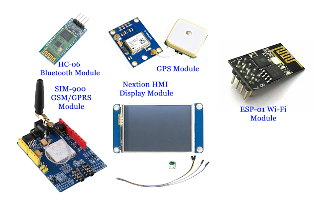
Many microcontroller external add-on modules use USART communication protocol as in an example of the popular GSM modem module.
ATMega32 AVR Universal Asynchronous Receiver Transmitter (UART)
Some UART based communication devices

These devices use their commands for example the AT command for GSM and Bluetooth module, the display instructions for the Nextion HMI display module.

A host PC is an application of the personal computer based control and instrumentations. However the original PC interface to the MCU USART requires and RS-232 voltage level. It is a long range data communication method. 
A PC Serial Port comes with a Desktop PC

To make a communication between a host PC and MCU USART, it requires a voltage level converter module as an instant the MAX-232 bridge.

MAX232 adapter board on an online market 
place

The RS-232 has a voltage level of +/-12V while the MCU USART has a TTL +5V voltage level.

However due to the advancement of the semiconductor chip developments, the old PC serial port could be replace with the USB-Serial converter chip at a lower cost and ease of use - for example the FT-232 from the FDI semiconductor. 

FT232 USB-Serial converter module from an online market place

These chips work at 5V TTL and 3.3V supply and communication voltage level.

AVR Programming For The USART

To program the USART module of the AVR ATMega32 we must initialize the module first.
  1. set the numbers of the data bits
  2. set the numbers the stop bits
  3. enable or disable the parity checker
  4. Select and appropriate baud rate by working with the UBRR register.
To send and receive the UART data we must follow the following steps,
  1. enable the receiver and the transmitter
  2. put the data into the UDR register
  3. wait until the completion
Optionally we can use the USART interrupt to more efficient in timing of the operation.

An MCU Transmitter Example

For an introductory example we demonstrate how to configure the USART as a transmitter that send some characters to the PC UART terminal.

/*
 * uart_basic.c
 *
 * Created: 9/28/2020 8:19:06 PM
 * Author : aki-technical
 */ 

#include <avr/io.h>

#define F_CPU 16000000UL
#include <util/delay.h>

void uartInit(unsigned long baud){
unsigned int UBRR;
/*Baud rate calculator*/
UBRR=(F_CPU/(16*baud))-1;
UBRRH=(unsigned char)(UBRR>>8);
UBRRL=(unsigned char)UBRR;
/*Enable the transmitter and receiver*/
UCSRB=(1<<RXEN)|(1<<TXEN);
/*asynchronous mode, 8-bit, 1-stop bit*/
UCSRC=(1<<URSEL)|(1<<UCSZ1)|(1<<UCSZ0);
}

void uartTransmit(unsigned char data){
/*Stay here until the buffer is empty*/
while(!(UCSRA&(1<<UDRE)));
/*Put the data into the buffer*/
UDR=data;
}

int main(void)
{
    uartInit(9600);
    uartTransmit('H');
    uartTransmit('i');
    while (1) 
    {
    }
}

Click here to download zip file of this working example.

ATMega32 AVR Universal Asynchronous Receiver Transmitter (UART)
Schematic Diagram

The schematic shows only a virtual terminal that could emulate the host PC serial port.

A C Pointer Example

With the advantage of using the C pointer the numbers of character is flexible in sizing. We can send a string of character to the UART transmitter.

/*
 * uart_basic_with pointer.c
 *
 * Created: 9/29/2020 7:05:51 PM
 * Author : aki-technical
 */ 

#include <avr/io.h>

#define F_CPU 16000000UL
#include <util/delay.h>

void uartInit(unsigned long baud){
unsigned int UBRR;
/*Baud rate calculator*/
UBRR=(F_CPU/(16*baud))-1;
UBRRH=(unsigned char)(UBRR>>8);
UBRRL=(unsigned char)UBRR;
/*Enable the transmitter and receiver*/
UCSRB=(1<<RXEN)|(1<<TXEN);
/*asynchronous mode, 8-bit, 1-stop bit*/
UCSRC=(1<<URSEL)|(1<<UCSZ1)|(1<<UCSZ0);
}

void uartTransmit(unsigned char data){
/*Stay here until the buffer is empty*/
while(!(UCSRA&(1<<UDRE)));
/*Put the data into the buffer*/
UDR=data;
}

void sendText(char *txt){
while(*txt) uartTransmit(*txt++);
}

int main(void)
{
uartInit(9600);
sendText("Hello From ATMega32 AVR!");
while (1)
{
}
}

Click here to download the zip file of this working example. The schematic diagram remain the same as the previous one's.

ATMega32 AVR Universal Asynchronous Receiver Transmitter (UART)
UART with C pointer example

USART Receive and Transmit Example

The receiver of the USART can be enabled by setting the RXEN to '1'. To get the data from the USART receiver the program must test the UDRE bit until it's empty then the data can be read from the UDR.

In this example the host PC terminal send the character to the MCU USART then it echo the character to the host PC again.

/*
 * uart_Tx_Rx.c
 *
 * Created: 9/29/2020 7:18:40 PM
 * Author : aki-technical
 */ 

#include <avr/io.h>

#define F_CPU 16000000UL
#include <util/delay.h>

void uartInit(unsigned long baud){
unsigned int UBRR;
/*Baud rate calculator*/
UBRR=(F_CPU/(16*baud))-1;
UBRRH=(unsigned char)(UBRR>>8);
UBRRL=(unsigned char)UBRR;
/*Enable the transmitter and receiver*/
UCSRB=(1<<RXEN)|(1<<TXEN)|(1<<RXEN);
/*asynchronous mode, 8-bit, 1-stop bit*/
UCSRC=(1<<URSEL)|(1<<UCSZ1)|(1<<UCSZ0);
}

void uartTransmit(unsigned char data){
/*Stay here until the buffer is empty*/
while(!(UCSRA&(1<<UDRE)));
/*Put the data into the buffer*/
UDR=data;
}

 unsigned char uartReceive(){
/*Wait until the buffer is full*/
while(!(UCSRA&(1<<RXC)));
/*Get the data ready to use*/
return UDR;
}

void sendText(char *txt){
while(*txt) uartTransmit(*txt++);
}

int main(void)
{
char tmp;
DDRC=0xFF;
uartInit(9600);
sendText("ATMEGA32 AVR UART Receive/Transmit Example.\n\r");
while (1)
{
tmp=uartReceive();
PORTC=tmp;
uartTransmit(tmp);
}
}

The schematic diagram a little add-on.

ATMega32 AVR Universal Asynchronous Receiver Transmitter (UART)
Schematic Diagram

Click here to download the zip file of this working example.

Thursday, September 10, 2020

ATMega32 TWI interfaces to MCP23017 I2C I/O expanding

Overview

MCP23017 is a 16-bit microprocessor digital I/O expander, built up with two 8-bit GPIO ports. The inputs/outputs are bi-directional. I/O direction is controlled by its data direction control register that's similar to one's in its PICMicro device.

This device is required in any applications that the MCU has used up its digital I/O. For example, a master MCU need to toggle 16 output relays. The manufacturer has released an example of using this device to create a matrix keypad.

I/O Pins

The I/O expander also support interrupt whenever the logic inputs changed.

ATMega32 TWI interfaces to MCP23016 I2C I/O expander
MCP23017-E/SP I use for my prototyping
MCP23017 Pin Diagram

I make a summary of this 28-pin device:

  • 1 to 8 : 8-bit GPIOB port, ranges from GPB0 to GPB7.
  • 9 : VDD - positive supply voltage (2.0 to 5.5 V)
  • 10 : VSS - Supply ground
  • 11 : NC - Not Connected
  • 12 : SCK - Serial Clock
  • 13 : SDA - Serial Data
  • 14 : NC - Not Connected
  • 15 16 17 : A0 A1 A2 - I2C optional address select pins (must be properly wired between GND and VDD)
  • 18 : RESET - Active low reset pin
  • 19 20 : INTB INTA - Digital input change interrupt trigger pin.
  • 21 to 28 : 8-bit GPIOA port, ranges from GPB0 to GPB7.

Two-wire Serial Communication (TWI)

Using I2C (or TWI), this device could clock up to 1700 kHz. It's supplied from 2.0 to 5.5 V, but for most of electronics hobbyist a 5.0 V supply voltage is a preference. 

Just like other TWI devices, MCP23017 read and write operations are similar. This device contain I/O port register, output register, interrupt control registers etc.

MCP23017 Register Addresses

These registers could locate at both banks - bank 0 and bank 1 with different location. By default, without any control register setting, it locate at bank 0.

TWI Writting 

The writing address of MCP23017 is 01000000 in binary. To write to this device,
  1. initiate a start condition
  2. write 01000000 for MCP23017 slave writing
  3. write the address of a specific register we want to send data to
  4. write any data to that register
  5. send a stop condition
The register we select has its own address list in the table above. For example we want to enable the interrupt on the input port.

TWI Reading

The reading address of MCP23017 is 01000001 in binary. To read to this device,
  1. initiate a start condition
  2. write 01000001 for MCP23017 slave reading
  3. write the address of a specific register we want to read from
  4. Read the TWI TWDR register
  5. send a stop condition

Interfacing and Programming In Atmel Studio 7

A communication interface from a master MCU to MCP23017 uses only two wires - SCL and SDA. Most of TWI slave device left these two pins in open-drain, requires two external pull up resistor with a resistance between 4.7 kOhm to 10 kOhm.

However, ATMega32 pins can be pulled high via software. Hence, it eliminates the requirement of adding two external resistors for TWI communication.

In this example, I only make a basic digital I/O reading and writing without using any interrupt features.

ATMega32 TWI interfaces to MCP23017 I2C I/O expander
A running program

GPIOx configured as input while GPIOx configured as output. There direction control registers are IODIRA and IODIRB respectively. Both GPIOx ports have their own internal weak pull up resistors name as GPPUA and GPPUB for both ports. 

Reading from GPIOx to get its inputs status. Writing to OLATx register to send digital data to GPIO output registers.

The sample program as shown above, GPIOA configured as digital inputs. I turn on its internal weak pull up resistor. GPIOB configured as digital output port. The main program just reads digital input from GPIOA, and send the result to GPIOB.

Source Code

/*
 * i2c_mcp23017.c
 *
 * Created: 9/9/2020 6:47:16 PM
 * Author : aki-technical
 */ 

#include <avr/io.h>

#define F_CPU 16000000UL
#include <util/delay.h>

#define mcp23017Read 0b01000001
#define mcp23017Write 0b01000000

void i2cInit(void){
TWSR=0x03; //Bit Rate Pre-scaler Is 1:64
TWBR=0x0F;
TWCR=(1<<TWEN); //Enable The TWI Module
PORTC|=(1<<0);
PORTC|=(1<<1);
}

void i2cStart(void){
TWCR=(1<<TWINT)|(1<<TWSTA)|(1<<TWEN);
while((TWCR&(1<<TWINT))==0);
}

void i2cWrite(unsigned char data){
TWDR=data;
TWCR=(1<<TWINT)|(1<<TWEN);
while((TWCR&(1<<TWINT))==0);
}

unsigned char i2cRead(char ACK){
if(ACK==0)
TWCR=(1<<TWINT)|(1<<TWEN)|(1<<TWEA);
else
TWCR=(1<<TWINT)|(1<<TWEN);
while((TWCR&(1<<TWINT))==0);
return TWDR;
}

void i2cStop(){
TWCR=(1<<TWINT)|(1<<TWEN)|(1<<TWSTO);
}

/*GPIO A and B Direction Control Register*/
const char IODIRA = 0x00;
const char IODIRB = 0x01;
/*GPIOA PULL UP REGISTER CONTROL*/
const char GPPUA  = 0x0C;
/*GPIOA I/O PORT register*/
const char GPIOA  = 0x12;
/*GPIOB Output Register*/
const char OLATB  = 0x15;

/*MCP23017 Configuration Setting*/
void mcp23017Config(char address,char config){
i2cStart();
/*Select the write address*/
i2cWrite(mcp23017Write);
/*Select a register address*/
i2cWrite(address);
/*Send configuration data*/
i2cWrite(config);
i2cStop();
}

/*Read Data From MCP23017*/
unsigned char mcp23017Return(char address){
/*Select a specific address*/
i2cStart();
i2cWrite(mcp23017Write);
i2cWrite(address);
i2cStop();
/*Read data from the given address*/
i2cStart();
i2cWrite(mcp23017Read);
unsigned char i2cData=i2cRead(1);
i2cStop();
return i2cData;
}
int main(void)
{
unsigned char i2cData;
i2cInit();
/*Pull SCL and SDA high*/
PORTC=0x03;
/*Set GPIOA To Input*/
mcp23017Config(IODIRA,0xFF);
/*Set GPIOB To Output*/
mcp23017Config(IODIRB,0x00);
/*Turn On Pull Up Resistors On GPIOB*/
mcp23017Config(GPPUA,0xFF);

_delay_ms(10);
while (1)
{
/*Read digital input from GPIOA*/
i2cData=mcp23017Return(GPIOA);
/*Send it back to GPIOB*/
mcp23017Config(OLATB,i2cData);
_delay_ms(10);
}
}

Schematic Diagram

ATMega32 TWI interfaces to MCP23017 I2C I/O expander
Schematic Diagram - The master TWI doesn't use any other digital I/O rather than its TWI pins.

Click here to download the zip file of this example project.


If you want a standard PCB for ATMega32 micro-controller, you can order my AVR Microcontroller project from PCBWay with a reasonable price. Click here to get a free $5 credit for new account.


Search This Blog

Labels

25AA010A (1) 8051 (7) 93AA46B (1) ADC (30) Analog Comparator (1) Arduino (15) ARM (6) AT89C52 (7) ATMega32 (56) AVR (57) CCS PICC (28) DAC (1) DHT11 (2) Display (105) Distance Sensor (3) DS18B20 (3) dsPIC (2) dsPIC30F1010 (2) EEPROM (5) Environment Sensor (4) esp8266 (1) I2C (29) Input/Output (67) Interrupt (19) Keil (5) Keypad (10) LCD (47) Master/Slave (1) MAX7221 (1) MCP23017 (5) MCP23S17 (4) Meter (3) MikroC (2) Motor (15) MPLABX (71) Nokia 5110 LCD (3) OLED (2) One-Wire (6) Oscillator (8) PCB (6) PCD8544 (3) PCF8574 (5) PIC (107) PIC12F (2) PIC16F628A (2) PIC16F630 (1) PIC16F716 (3) PIC16F818 (10) PIC16F818/819 (2) PIC16F84A (15) PIC16F876A (1) PIC16F877A (9) PIC16F88 (1) PIC16F887 (60) PIC18 (19) PIC18F1220 (4) PIC18F2550 (3) PIC18F4550 (12) PWM (11) RTC (8) Sensor (10) SH1106 (1) Shift Register (11) Shift Registers (3) SPI (24) STM32 (6) STM32 Blue Pill (6) STM32CubeIDE (6) STM32F103C8T6 (6) SysTick (3) temperature sensor (11) Thermometer (21) Timer/Counter (31) TM1637 (2) UART (7) Ultrasonic (4) Voltmeter (7) WDT (1) XC16 (2) XC8 (94)