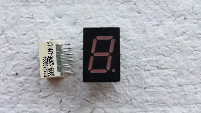
Seven Segment Display (SSD) is a classical display device for low end digital electronic equipment. The programming for is very simple. It could represent numbers and some English letters.
It come with two terminology, common cathode type and common anode type. But deciding which type to use depends on the application. In this example, I take only common cathode type.
 |
| single digit seven segments display |
 |
| Segment LED diagram |
Since it made of seven LED segment, we just turn on any LED to display digit or letter. For example, turning on LED segment B and C make digit "1" to display.
In the programming, they commonly use hexadecimal equivalent to the SSD output.
For the common cathode type display the hex code represent the digit from 0 to 9 and from A to F is shown below:Each LED segment made of from LED, requiring around 2 V and ~10 mA of current. Typically, the digital output from microcontroller drives a voltage of +5V TTL. So we need to cut down the voltage from microcontroller to ~2 V via resistor.
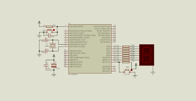
In this example, RD0 to RD6 used to interface with single digit seven-segment display. RD7 used as digital input, counting the number of pressed from the button
The maximum counting is 16 pulses.
 |
| The PIC16F887 CPU clocks at 4 MHz. It's supplied at +5 V DC. PortD RD0 to RD6 displays the counting result. PortD RD7 listens to the input counting. |
Source code is written using XC8.
#include<xc.h>
// PIC16F887 Configuration Bit Settings
// CONFIG1
#pragma config FOSC = XT
#pragma config WDTE = OFF
#pragma config PWRTE = OFF
#pragma config MCLRE = ON
#pragma config CP = OFF
#pragma config CPD = OFF
#pragma config BOREN = ON
#pragma config IESO = ON
#pragma config FCMEN = ON
#pragma config LVP = ON
// CONFIG2
#pragma config BOR4V = BOR40V
#pragma config WRT = OFF
/*_XTAL_FREQ use for __delay*/
#define _XTAL_FREQ 4000000
//Label a button a RD7
#define pressCounter RD7
void main(){
    /*SEVEN SEGMENT MAP FOR COMMON
    CATHODE TYPE SEVEN-SEGMENT DISPLAY*/
    unsigned char ssd[16]={0x3F,0x06,0x5B,0x4F,0x66,0x6D,0x7D,
        0x07,0x7F,0x6F,0x77,0x7C,0x39,0x5E,0x79,0x71};
    unsigned char btnCount=0;
    //Clear PortD
    PORTD=0x00;
    //Set RD7 to Digital Input
    TRISD=0x80;
    while(1){
        if(pressCounter==0){
            __delay_ms(250);
            btnCount+=1;
        }
        if(btnCount>15) btnCount=0;
        PORTD=ssd[btnCount];
    }
}
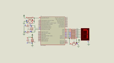
I took a screen shot of the simulation.
 |
| While the simulation. The counting reaches seven. The SSD display the counting result. |
No comments:
Post a Comment