In control application, date and time data is play an important role in any situation where such as scheduling daily task.
A real time clock (RTC) module stores date and time data, required by the controller. It could be integrated in an MCU, or could be a discrete IC.
A discrete RTC available in many packages and communication interfaces. Those interfaces are SPI(Serial Peripheral Interface) and I2C(Inter-Integrated Circuit). The I2C has an advantage of using two wires communication lines, the data line, and the clock line.
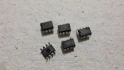
DS1307 is a popular RTC integrated circuit. It is an 8-pin DIP package, suitable for hobbyist prototyping.
It uses the I2C communication interface.
Some DIP package of DS1307 I2C real time clock |
To interface to the ds1307, we need a master MCU with an I2C built-in. Unfortunately, the PIC16F84A MCU doesn't have the I2C module inside.
Fortunately, the CCS PICC compiler has a software library to implement the I2C protocol. Overall process implemented using software bit banging. Bit banging has some disadvantage such as consuming the CPU time and need more program space.
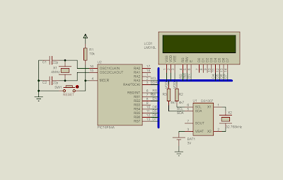
Simulation preview, The ds1307 interface to PIC16F84A via RA3 and RA4. |
The source code is written using CCS PICC compiler.
#include<16F84A.h>
#fuses XT,NOWDT
#use delay(clock=4M)
#use I2C(master,scl=PIN_A3,SDA=PIN_A4)

#define LCD_RS_PIN      PIN_B0
#define LCD_RW_PIN      PIN_B1
#define LCD_ENABLE_PIN  PIN_B2
#define LCD_DATA4       PIN_B4
#define LCD_DATA5       PIN_B5
#define LCD_DATA6       PIN_B6
#define LCD_DATA7       PIN_B7
#include<lcd.c>
char bcd2Dec(char input){
   char tmp=((input>>4)*10)+(input&0x0F);
   return tmp;
}
void ds1307SetAddress(char address){
   i2c_start();
   i2c_write(0b11010000);     //DS1307 Write Address
   i2c_write(address);        //Set the second register

}
char ds1307ReadTime(void){
   i2c_start();               //Issue a repeated start
   i2c_write(0b11010001);     //DS1307 Read Address
   char Data=i2c_read(FALSE);   //Read Data From Address Without ACK
   i2c_stop();
   return bcd2dec(Data);

}
void main(){
   byte secondData,minuteData,hourData;
   byte days,dayOfWeek,dates,years;

   lcd_init();

   while(1){

      ds1307SetAddress(0);
      secondData=ds1307ReadTime();
      ds1307SetAddress(1);
      minuteData=ds1307ReadTime();
      ds1307SetAddress(2);
      hourData=ds1307ReadTime();
      /*********************************/
      ds1307SetAddress(3);
      dayOfWeek=ds1307ReadTime();
      ds1307SetAddress(4);
      days=ds1307ReadTime();
      ds1307SetAddress(5);
      dates=ds1307ReadTime();
      ds1307SetAddress(6);
      years=ds1307ReadTime();
      /********************************/

      lcd_gotoxy(1,1);
      printf(LCD_PUTC,"%d:%d:20%d ",days,dates,years);
      lcd_gotoxy(12,1);
      switch(dayOfWeek){
         case 1:
             printf(LCD_PUTC,"Sun");
             break;

         case 2:
             printf(LCD_PUTC,"Mon");
             break;

         case 3:
             printf(LCD_PUTC,"Tue");
             break;

         case 4:
             printf(LCD_PUTC,"Wed");
             break;

         case 5:
             printf(LCD_PUTC,"Thu");
             break;

         case 6:
             printf(LCD_PUTC,"Fri");
             break;

         case 7:
             printf(LCD_PUTC,"Sat");
             break;
      }

      lcd_gotoxy(1,2);
      printf(LCD_PUTC,"Time: %d:%d:%d ",hourData,minuteData,secondData);
      delay_ms(1000);
   }
}
Full Schematic Diagram:
Full diagram, The PIC16F84A CPU supplied by +5V DC voltage, clocked at a 4 MHz crystal oscillator. The LCD interface is 4-bit connects to PORTB. The ds1307 interface to PIC16F84A via RA3 and RA4. The clock frequency is 32.768 kHz. Battery Bat1 uses to keep the RTC alive. |


No comments:
Post a Comment