 |
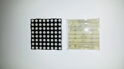
| Internal arrangement of the 8x8 led matrix, common cathode Each row make a common of LED anode Each column make a common of LED cathode |
For a simple programming interface, A character pattern are 8x8. To display information, we display the pattern row by row. Each row active for about 1 ms.
In the example below, I display a character 'A' on the LED matrix. I use Microsoft Excel to generate character data.
 |
| using Excel worksheet to make dot matrix character |
 |
| PORTD is use to generate row character pattern, PORTC is use to enable each column |
Source code:
#include <avr/io.h>

#define F_CPU 16000000UL
#include "util/delay.h"

#define dTime 1

char letterA[8]={0x10,0x38,0x6C,0xC6,0xC6,0xFE,0xC6,0xC6};

char dotControl[8]={1,2,4,8,16,32,64,128};

int main(void)
 {
     DDRD=0xFF;
     DDRC=0xFF;
     while (1)
     {
     for (int i=0;i<8;i++)
     {
     PORTD=0x00;
     PORTC=letterA[i];
     PORTD=dotControl[i];
     _delay_ms(dTime);
     }
   }
}
Click here to download its source file.Back to main tutorial page ATMega32 tutorials in C with Atmel Studio 7.

you should comment each line code
ReplyDeleteOh on newer post I put comment on code. Thanks for your comment.
ReplyDeletei really like this article please keep it up. g6e 134pl st us dc12
ReplyDeleteHi, Thanks for visiting my blog.
DeleteYour blog is a fantastic resource, offering insightful and well-researched content. The way you break down topics makes it easy to understand, yet it remains engaging for more knowledgeable readers. I always look forward to your posts as they consistently provide valuable perspectives. Keep up the great work—your efforts are truly making a difference! Enrgtech
ReplyDeleteDot Matrix Display
Always clean and restocked. where can i buy a vending machine
ReplyDelete