Introduction
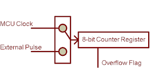
Timer/counter 0 of ATMega32 is an 8-bit register store the input counting. The input could be fed from MCU clock source, or could be fed from external pulse at T0 (pin PB0) .
We call it timer 0 when the clock source is fed from the MCU clock. While calling it counter 0 whenever the clock source is fed from T0 pin.
 |
| Scheme of Timer/Counter 0 |
- generating time delay
- generating frequency output
- external pulse counting
- measuring input pulse width
To program using timer/counter 0 we have access its related registers from the SFR. Registers related with timer/counter 0 are:
- Timer/Counter Control Register 0 (TCCR0)
- Timer/Counter Register (TCNT0)
- Timer/Counter Interrupt Mask Register(TIMSK)
- Timer/Counter Interrupt Flag Register (TIFR)
- Special IO Register (SFIOR)
In programming with timer/counter 0 we use some or all of them, depend on the given task. They are 8-bit wide. To get all details about them, please check the device's datasheet. We can not list them here.
Generating a frequency output using timer 0
In this example, I use timer 0 mode to count the clock pulse of the MCU. The TCNT0 is an 8-bit register, ranges from 0x00 to 0xFF. TCNT0 is increment on every clock pulse of the MCU clock (1:1 prescaler). When it is overflow, the timer 0 overflow flag will be set.
By default, timer/counter is configured as timer, but stopped working. To make it run, we must set the clock source prescaler in the TCCR0.
- Timer/Counter Control Register 0 (TCCR0)
| BIT 7 | BIT 0 | ||||||
| FOC0 | WGM00 | COM01 | COM00 | WGM01 | CS02 | CS01 | CS00 |
Timer 0 clock select bit CS is 3-bit wide CS02:00. It is used for selecting the prescaler from 1:1 to 1:1024. Additionally, it used for setting the external pulse counting.
- Timer/Counter Interrupt Flag Register (TIFR)
| BIT 7 | BIT 0 | ||||||
| OCF2 | TOV2 | ICF1 | OCF1A | OCF1B | TOV1 | OCF0 | TOV0 |
- Timer/Counter Register (TCNT0)
| BIT 7 | BIT 0 | ||||||
| D7 | D6 | D5 | D4 | D3 | D2 | D1 | D0 |
 |
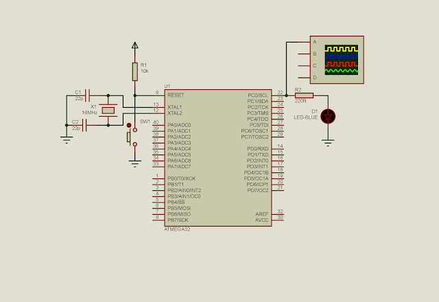
| Schematic Diagram. ATMega32 clocks at 16 MHz. PC0 toggles an output LED. A virtual oscilloscope track the output signal. |
#include <avr/io.h>
int main(void)
{
    //Set PortC to Output
 DDRC=0xFF;
 //Clear PortC
 PORTC=0x00;
 //Set 1:1 prescaler
 TCCR0=0x01;
 //Clear overflow flag
 TIFR=0x01;
    while (1)
    {
  //Check if TIFR is set
  if(TIFR&0x01){     //Toggle PC0
   PORTC^=1;
   //Preload TCNT0
   TCNT0=-16;
   //Clear flag
   TIFR=0x01;
  }
    }
}
 |
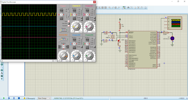
| Generating a square wave using timer 0. PC0 toggles every 1 micro second. So the period is 2 micro seconds, giving the frequency of 500 kHz. |
Back to main tutorial page ATMega32 tutorials in C with Atmel Studio 7.
Click here to download source file of this programming example.
No comments:
Post a Comment