Monday, February 28, 2022

PIC16F877A Timer0 Programming in XC8

Timer 0 of PIC16F877A could operate in timer mode, or counter mode. In timer mode, it can create timing delay, measuring the period of external event, etc. In counter mode, it can store the number of pulse enter its clock in pin.
 

PIC16F877A Timer0 Programming in XC8
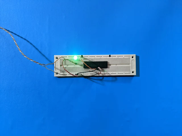
Experiment on breadboard

In this example, I will use this timer 0 to operate in timer mode. It's use to create a timing delay that generate an output frequency of 1
Hz, blinking an output LED. The LED toggles for every 500 mS.


PIC16F877A Timer0 Programming in XC8
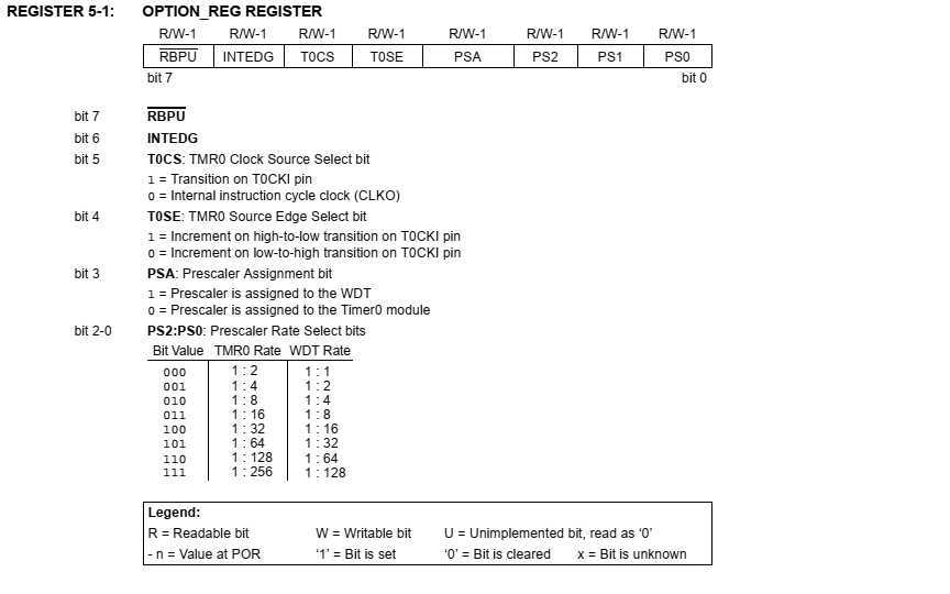
Option register details

I clear the TMR0 Clock Source Select bit (T0CS), allowing it to operate in timer mode. The Prescaler Assignment bit (PSA) is clear, forcing the prescaler to TMR0 rate at maximum delay. Then the Prescaler Rate Select bits are assigned to "111". So the prescaler is 1:256.

The micro-controller clock frequency is 20 MHz. The instruction frequency is 1/20 MHz = 5 MHz. Hence the final period is 1/5 MHz = 200 nano-seconds.

With the prescaler of 1:256, then the timer 0 clock rate is 256 * 200 nano-seconds = 51.2 micro-seconds.

I will need to create a variable that count the timer rate up to 10 micro-seconds. Because the TMR0 is only 8-bit (256 values in total).

10 micro-seconds = cnt  * (51.2 micro-seconds) then
cnt = (10 milliseconds)/(51.2 micro-seconds) = (10 milliseconds)/(0.0512 milliseconds)
cnt = 195 counts.

So, the cnt is needed to increase 50 times more to make a 500 mS delay time.

Source Code:

  1. /*
  2.  * PIC16F887 Timer 0 programming
  3.  */
  4. #include <xc.h>
  5. #include "config.h"
  6.  
  7. #define LED RB0
  8.  
  9. int main(void){
  10. unsigned int cnt=0;
  11. PORTB=0x00;
  12. TRISB0=0;
  13. //select internal instruction cycle clock
  14. T0CS=0;
  15. //Select timer 0 prescaler
  16. PSA=0;
  17. //select 1:256 prescaler
  18. OPTION_REGbits.PS=0x07;
  19. TMR0=0;
  20. while(1){
  21. if(TMR0>=200){
  22. cnt++;
  23. TMR0=0;
  24. }
  25. if(cnt>=50){
  26. LED^=1;
  27. cnt=0;
  28. }
  29. }
  30. }

Schematic:

PIC16F877A Timer0 Programming in XC8
Schematic Diagram

Click here to download its source file.


Search This Blog

Labels

25AA010A (1) 8051 (7) 93AA46B (1) ADC (30) Analog Comparator (1) Arduino (15) ARM (6) AT89C52 (7) ATMega32 (56) AVR (57) CCS PICC (28) DAC (1) DHT11 (2) Display (105) Distance Sensor (3) DS18B20 (3) dsPIC (2) dsPIC30F1010 (2) EEPROM (5) Environment Sensor (4) esp8266 (1) I2C (29) Input/Output (67) Interrupt (19) Keil (5) Keypad (10) LCD (47) Master/Slave (1) MAX7221 (1) MCP23017 (5) MCP23S17 (4) Meter (3) MikroC (2) Motor (15) MPLABX (71) Nokia 5110 LCD (3) OLED (2) One-Wire (6) Oscillator (8) PCB (6) PCD8544 (3) PCF8574 (5) PIC (107) PIC12F (2) PIC16F628A (2) PIC16F630 (1) PIC16F716 (3) PIC16F818 (10) PIC16F818/819 (2) PIC16F84A (15) PIC16F876A (1) PIC16F877A (9) PIC16F88 (1) PIC16F887 (60) PIC18 (19) PIC18F1220 (4) PIC18F2550 (3) PIC18F4550 (12) PWM (11) RTC (8) Sensor (10) SH1106 (1) Shift Register (11) Shift Registers (3) SPI (24) STM32 (6) STM32 Blue Pill (6) STM32CubeIDE (6) STM32F103C8T6 (6) SysTick (3) temperature sensor (11) Thermometer (21) Timer/Counter (31) TM1637 (2) UART (7) Ultrasonic (4) Voltmeter (7) WDT (1) XC16 (2) XC8 (94)