In previous post, I showed the external interrupt programming of PIC16F877A. Here I use another interrupt source of PortB. It's Port B Interrupt on Change. This interrupt creates by any logic change between RB4 and RB7 of PortB.
To use this interrupt source, we must
1- Set any pins between RB4 and RB7 as a digital input.
2- Set its transition
3- Turn on PortB weak pull up resistors (optional)
4- Write the ISR
Simulation sample in Proteus 8 |
In this example, I use all PortB interrupt on change source from RB4 to RB7. These interrupt sources connect to input buttons. They will toggle RB1 and RB2. RB0 blinks an output LED regularly.
/* * PIC16F877a Port B Interrupt On Change * Example in xc8 */ #include <xc.h> // PIC16F877A Configuration Bit Settings // CONFIG #pragma config FOSC = HS #pragma config WDTE = OFF #pragma config PWRTE = OFF #pragma config BOREN = ON #pragma config LVP = OFF #pragma config WRT = OFF #pragma config CP = OFF #define _XTAL_FREQ 20e6 void main(void){ /*Clear IO port*/ PORTB=0x00; /*RB0...1 input*/ TRISB=0xF0; /*Turn on Pull Up Resistor*/ nRBPU=0; /*Turn On External Interrupt*/ RBIE=1; /*Turn On Global Interrupt*/ GIE=1; /*Clear Interrupt Flag*/ RBIF=0; while(1){ RB0^=1; __delay_ms(500); } } /*Interrupt Service Routine*/ void interrupt portBChange(void){ /*Check RB Port Change Interrupt Present*/ if(RBIE&&RBIF){ if(RB4^1) RB1=1; if(RB5^1) RB1=0; if(RB6^1) RB2=1; if(RB7^1) RB2=0; RBIF=0; } }
Its clock source is 20MHz from a crystal oscillator.
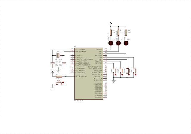
Schematic Diagram |
Click here to download source file.