Introduction
PIC16F877A was a popular 8-bit microcontroller for university students and hobbyists. It still useful for novice programmers learning to program microcontroller.
This device has digital I/O, analog input, Timer, PWM output, Communication, and other features.
 |
| PIC16F87XA devices Table |
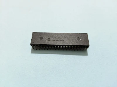
I select PIC16F877A-I/P in DIP package that ease of prototyping.
 |
| PIC16F877A 40-Pin DIP Package Pin Diagram |
 |
| PIC16F877A 40 pins DIP |
Architecture
It’s designed using Harvard architecture, separating between program and data memory. CPU fetches both data and program memory concurrently. Its pipe-lining technique make instruction execution archive at one CPU cycle, but it excepts some instructions that require more than one cycle.
Memory
Its program counter is 13-bit wide. Instruction length is 14-bit (called one word). It can address program memory of 8K x 14 program space. Reset vector locate at address 0000h. It has only one interrupt vector which locate at address 0004h.
 |
| PIC16F877A memory map and stack |
Stack used for calling and returning sub routine. It’s 8 levels, allowing up to 8 nested sub routine calling. Nested calling more than this value, making program unpredictable.
Coding PIC16F877A
Assembly language is core programming for microcontroller. It’s preferred for most of university program. It’s essential for programmer to understand overall operation of microcontroller before allowing to program in Assembly language.
Assembly language is free offered by device’s manufacturer. Programming made from this language composes of a lot of lines. It consumes a very long time to complete a program using this language. Updating and modifying program is very hard.
However microcontroller program written in Assembly language is very effective in program memory. Program execution is very fast.
Modern embedded C compilers for PIC microcontroller is very popular now. Even small 8-bit microcontroller implemented using C regardless of its program memory space – for example PIC microcontroller with 1KB of program memory. I see only a few of C compilers in market,
- MikroC
- CCS PICC
- XC8
XC8 integrated in MPLABX IDE from Microchip Technology. It has a free version without limitation.
Getting Started With C Using XC8
Toggling digital I/O is a good getting-started section for most of microcontroller new learner. It allow us to test its normal operation.
Hardware
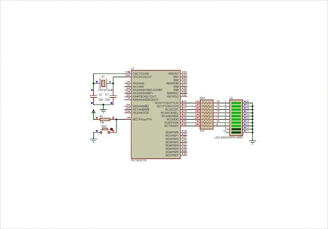
PIC16F877A supplies at +5V DC with its clocking input of 20MHz, from external crystal oscillator. Port C connects to 8 LED outputs via a resistor network.
 |
| Schematic Diagram |
In Proteus, power supply pins are hidden but they internally wired by this simulator program.
C Programmer
This getting started program made of a little lines of code. Device configuration section seem very long due XC8 compiler directives. Port C toggles its output with a delay of one second.
This program consumes about 1% of memory resource.
 |
| Statistic in MPLABX IDE dashboard |
Click here to download this example package.


