Introduction
Typically a microcontroller requires an external reset pin as an example of the Master Clear (MCLR) pin of PIC microcontroller. Some PIC device have an optional function on this reset pin, as an example of PIC16F818.
Pin RA5 of Port B is multiplexed with Master Clear module input. This reset pin could be turned off, and could be used as a digital input pin via software setting.
Configuration Register of PIC16F818
First, we need to turn MCLR function in the Configuration register off.
 |
| PIC16F818/819 Configuration Register addresses at 2007h |
MCLRE is bit 5 of this configuration register. Clearing this bit to disable the MCLRE input function.
 |
| MCLRE selection bit |
Port Setting
Additionally, Port A of PIC16F818 is multiplexed with analog input function (10-bit ADC Module). Embedded programmer need to clear the analog input function to enable the digital I/O mode.
 |
| ADCON1 – A/D Control Register 1 addresses at 9Fh |
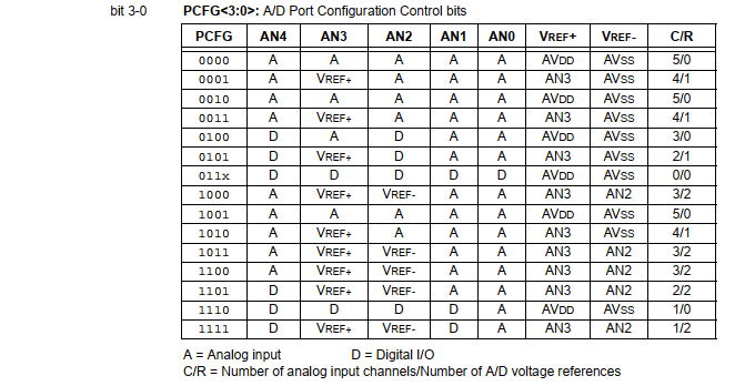
The A/D Port Configuration Control bits of ADCON1 register must be set to 0x06 to enable all digital I/O on Port A. And then the user is able to use this digital input pin.
 |
| A/D Port Configuration Control bits of ADCON1 |
Next we are going to code this example.
Programming for MCLRE Digital Input Using XC8
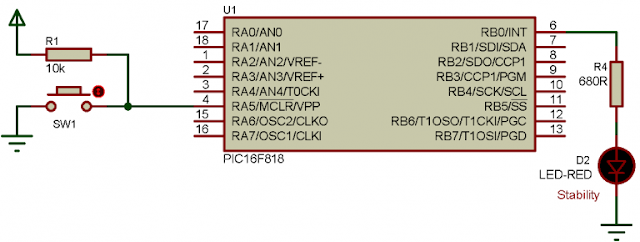
This example, the controller toggle an output LED connects to RB0. Pin RA5/MCLRE is a digital input. Whenever it’s pressed, the controller waits until it’s released. After that the controller toggles RB0.
Schematic for Software Simulation
We prepare a circuit diagram for this example in simulator. It can be used in both reference circuit and simulation on PC.
 |
| Schematic diagram for this example |
Here a push button SW1 that connect to RA5 is not an external reset circuit for the controller. It’s a digital input pin. Pressing this switch doesn’t reset the microcontroller.
XC8 Programming in MPLABX IDE
Using embedded to code an 8-bit microcontroller, the main source code made of a little lines of code.
XC8 Example of disabling the
* Master Clear Input pin and
* used it as a digital input
*/
#include <xc.h>
// PIC16F818 Configuration Bit Settings
// CONFIG
#pragma config FOSC = INTOSCIO // Oscillator Selection bits (INTRC oscillator; port I/O function on both RA6/OSC2/CLKO pin and RA7/OSC1/CLKI pin)
#pragma config WDTE = OFF // Watchdog Timer Enable bit (WDT disabled)
#pragma config PWRTE = OFF // Power-up Timer Enable bit (PWRT disabled)
#pragma config MCLRE = OFF // RA5/MCLR/VPP Pin Function Select bit (RA5/MCLR/VPP pin function is digital I/O, MCLR internally tied to VDD)
#pragma config BOREN = ON // Brown-out Reset Enable bit (BOR enabled)
#pragma config LVP = OFF // Low-Voltage Programming Enable bit (RB3/PGM pin has digital I/O function, HV on MCLR must be used for programming)
#pragma config CPD = OFF // Data EE Memory Code Protection bit (Code protection off)
#pragma config WRT = OFF // Flash Program Memory Write Enable bits (Write protection off)
#pragma config CCPMX = RB2 // CCP1 Pin Selection bit (CCP1 function on RB2)
#pragma config CP = OFF // Flash Program Memory Code Protection bit (Code protection off)
/*Button and LED Label*/
#define buttonInput RA5
#define outputLed RB0
/*oscillator enumeration*/
enum intOscFreq{_31kHz=0,_125kHz,_250kHz,_500kHz,_1MHz,_2MHz,_4MHz,_8MHz=7};
/*Internal oscillator selection routine*/
void oscConfig(char oscFreq){
OSCCONbits.IRCF=oscFreq;
}
void main(void){
/*Oscillator Setting Up*/
oscConfig(_4MHz);
/*Clear Analog Input on Port A*/
ADCON1=0x06;
/*Clear I/O*/
PORTB=0x00;
PORTA=0x00;
/*Input Button*/
TRISAbits.TRISA5=1;
/*Ouput LED*/
TRISBbits.TRISB0=0;
while(1){
/*Check if button pressed*/
if(buttonInput==0){
/*Wait until it's released*/
while(buttonInput==0);
/*Toggle LED*/
outputLed^=1;
}
}
}
This example use the internal oscillator of PIC16F818. For more information about accessing its internal oscillator click here.
Prototyping on Breadboard
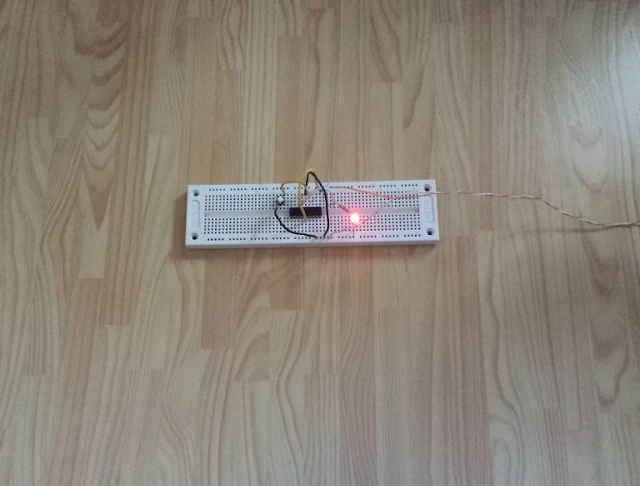
I wired this example on breadboard due to its simplicity. I worked like the one’s tested in Proteus simulator. Click here to download source file.
 |
| Prototyping on breadboard |