Interrupt is a hardware event notification to the CPU. When an interrupt occurs, we could ignore, or process it via software. Interrupt is fast.
Using the interrupt, we no need to wait for any event in the program main loop. We can keep the program main loop do other task. Interrupt makes the program more responsive.
To enable interrupt we must enable the global interrupt and related interrupt source, for example the external interrupt source.
When an interrupt occurs, the program counter jumps to the interrupt vector 0x04. Mid-range PIC like PIC16F887 has only one interrupt vector, that's 0x04.
An interrupt service routine (ISR) is a piece of code used to handle the interrupt. It must be written at the address 0x04. The ISR must be short because we don't want the program spend longer time at the interrupt.
In the low level programming language like Assembly, we must have and restore the context of WREG and Status register due to interrupt. But in the high level language such as XC8 C compiler we no need to do this task.
In XC8, we write the ISR inside the special function called interrupt like below:
void interrupt _myISR(void){
    //write your ISR here.}
Pin RB0 of PORTB in PIC16F887 could generate an interrupt signal. When working with interrupt, RB0 is called INT (external interrupt).There are two modes of interrupt:
- interrupt on rising edge
- interrupt on falling edge
To program the external interrupt of PIC16F887, do the following steps:
- set RB0 as digital input
- select the external interrupt edge by INTEDG of the OPTION_REG
- enable the interrupt by setting INTE of the INTCON register to '1'
- enable the global interrupt by setting the GIE of INTCON register to '1'.
- keep the program main loop
- writing the interrupt service routine.
- in the interrupt service routine clear the INTF
The registers relate to external interrupt are:
- PORTB and TRISB
- ANSELH
- OPTION_REG
- INTCON
- WPUB(optional, use to pulling up)
INTEDG of the OPTION_REG uses to select the transition.
| BIT 7 | BIT 0 | ||||||
| nRBPU | INTEDG | T0CS | T0SE | PSA | PS2 | PS1 | PS0 |
When INTEDG=1, interrupt occurs on the rising edge of INT pin, otherwise interrupt occurs on the falling edge of the INT pin.
INTCON register contain the information and setting of interrupts.
| BIT 7 | BIT 0 | ||||||
| GIE | PEIE | T0IE | INTE | RBIE | T0IF | INTF | RBIF |
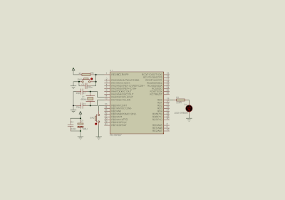
In this example, I use external interrupt to toggle the output pin at RD0.
 |
| Schematic diagram. SW2 connects to INT pin could create an interrupt signal from High to Low. D1 LED connects to RD0 will toggle each time the external interrupt occurred. |
Source code is written using XC8.
#include<xc.h>
// PIC16F887 Configuration Bit Settings
// CONFIG1
#pragma config FOSC = XT
#pragma config WDTE = OFF
#pragma config PWRTE = OFF
#pragma config MCLRE = ON
#pragma config CP = OFF
#pragma config CPD = OFF
#pragma config BOREN = ON
#pragma config IESO = ON
#pragma config FCMEN = ON
#pragma config LVP = ON
// CONFIG2
#pragma config BOR4V = BOR40V
#pragma config WRT = OFF
//LED connects to RD0
#define LED RD0
/*Interrupt service routine*/
void interrupt _ISR(void){
    /*looking for external interrupt
     by testing the INTF*/
    if(INTF){
        //Clear flag
        INTF=0;
        //toggle RD0
        LED^=1;
    }
}
void main(){
    /*clear PortB*/
    PORTB=0x00;
    /*clear PortD*/
    PORTD=0x00;
    /*PortD as output*/
    TRISD=0x00;
    /*PortB as input*/
    TRISB0=1;
    /*disable analog input at RB0*/
    ANS12=0;
    /*turn on global weak pull up*/
    nRBPU=0;
    /*Turn on pull up resistor at RB0*/
    WPUB0=1;
    /*enable external interrupt*/
    INTE=1;
    /*select interrupt at falling edge*/
    INTEDG=0;
    /*clear external interrupt flag*/
    INTF=0;
    /*enable global interrupt*/
    GIE=1;
    /*program main loop does nothing
     our could be anythings*/
    while(1);
}
The screen shot of the running program.
 |
| screen shot of the program simulation. RD0 toggles the output LED any time the external interrupt occurred. |
No comments:
Post a Comment