Sunday, April 26, 2020

Interfacing ATMega32 To Seven Segment Display


Seven Segment Display (SSD) is a classical display device for low end digital electronic equipment. The programming for is very simple. It could represent numbers and some English letters.

It come with two terminology, common cathode type and common anode type. But deciding which type to use depends on the application. In this example, I take only common cathode type.
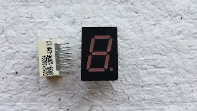
Single digit seven segments display
single digit seven segments display

LED segments configurations
Segment LED diagram


Since it made of seven LED segment, we just turn on any LED to display digit or letter. For example, turning on LED segment B and C make digit "1" to display.

In programming, they commonly use hexadecimal equivalent to the SSD output.

For the common cathode type display the hex code represent the digit from 0 to 9 and from A to F is shown below:


Each LED segment made of from LED, requiring around 2 V and ~10 mA of current. Typically, the digital output from microcontroller drives a voltage of +5V TTL. So we need to cut down the voltage from microcontroller to ~2 V via resistor.


Resistors are connected to cut down voltage output to common cathode SSD

In this example, I use a digital input from PD0 to count the event, and output the counting to the presented SSD.
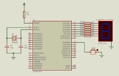

Circuit diagram uses for simulation

Source Code:
  1. #include <avr/io.h>
  2. #define F_CPU 16000000UL
  3. #include "util/delay.h"
  4. //SET THE INPUT BUTTON FOR COUNTING
  5. #define btnPressed ((PIND&0x01)==0)
  6. int main(void)
  7. {
  8. //SEVEN SEGMENT MAP FOR COMMON
  9. //CATHODE TYPE SEVEN SEGMENT DISPLAY
  10. unsigned char ssd[16]={0x3F,0x06,0x5B,0x4F,0x66,0x6D,0x7D,
  11. 0x07,0x7F,0x6F,0x77,0x7C,0x39,0x5E,0x79,0x71};
  12. unsigned char btnCount=0;
  13. DDRC=0xFF; //PORTC IS FOR OUTPUT TO SEVEN SEGMENT
  14. DDRD=0xFE; //PORTD PD0 IS USED FOR INPUT COUNTING
  15. PORTD=0x01; //SET PD0 TO HIGH FOR PULLING UP
  16. while (1)
  17. {
  18. if (btnPressed) //CHECK IF PD0 IS PRESSED
  19. {
  20. btnCount+=1; //Increase The Counter
  21. _delay_ms(250);
  22. if(btnCount>15) btnCount=0;
  23. //RESET COUNTER WHEN IT IS OVER 15
  24. }
  25. PORTC=ssd[btnCount]; //OUTPUT TO SSD
  26. }
  27. }

Back to main tutorial page ATMega32 tutorials in C with Atmel Studio 7.

Click here to download this example.

If you want a standard PCB for ATMega32 micro-controller, you can order my AVR Microcontroller project from PCBWay with a reasonable price. Click here to get a free $5 credit for new account.

Interfacing ATMega32 to 74HC595 shift register
ATMega16 ATMega32 Experiment Board PCB from PCBWay
 

No comments:

Post a Comment

Search This Blog

Labels

25AA010A (1) 8051 (7) 93AA46B (1) ADC (30) Analog Comparator (1) Arduino (15) ARM (6) AT89C52 (7) ATMega32 (54) AVR (57) CCS PICC (28) DAC (1) DHT11 (2) Display (105) Distance Sensor (3) DS18B20 (3) dsPIC (2) dsPIC30F1010 (2) EEPROM (5) Environment Sensor (4) esp8266 (1) I2C (29) Input/Output (67) Interrupt (19) Keil (5) Keypad (10) LCD (46) Master/Slave (1) MAX7221 (1) MCP23017 (5) MCP23S17 (4) Meter (3) MikroC (2) Motor (15) MPLABX (66) Nokia 5110 LCD (3) OLED (2) One-Wire (6) Oscillator (8) PCB (6) PCD8544 (3) PCF8574 (5) PIC (107) PIC12F (2) PIC16F628A (2) PIC16F630 (1) PIC16F716 (3) PIC16F818 (10) PIC16F818/819 (2) PIC16F84A (15) PIC16F876A (1) PIC16F877A (9) PIC16F88 (1) PIC16F887 (60) PIC18 (19) PIC18F1220 (4) PIC18F2550 (3) PIC18F4550 (12) PWM (11) RTC (8) Sensor (10) SH1106 (1) Shift Register (11) Shift Registers (2) SPI (24) STM32 (6) STM32 Blue Pill (6) STM32CubeIDE (6) STM32F103C8T6 (6) SysTick (3) temperature sensor (11) Thermometer (21) Timer/Counter (30) TM1637 (2) UART (7) Ultrasonic (4) Voltmeter (7) WDT (1) XC16 (2) XC8 (94)